UNEC Journal of Engineering and Applied Sciences Volume 5, No 1, pages 16-25 (2025) Cite this article, ![]() 1708 https://doi.org/10.61640/ujeas.2025.0502
1708 https://doi.org/10.61640/ujeas.2025.0502
Parabola solar heaters (Parabolic Solar Collectors) are one of the widely used technologies in modern energy systems that increase efficiency by converting solar energy into heat. One of the most important components in these systems are heat receivers. They receive sunlight and convert it into heat, and this heat is then transferred to various energy sources. In this analysis, the structure of heat receivers, the principle of operation, materials, and factors affecting efficiency are widely covered.
Modern technology development in the energy sector is aimed at improving energy efficiency and introducing renewable energy sources. In the context of increasing demand for environmentally friendly and sustainable energy, solar energy occupies a key place. Among the technologies using solar radiation, linear focusing solar collectors stand out for their ability to concentrate solar energy on a small area, which makes them indispensable in various industrial and household processes. These devices are used in hot water supply systems, thermal power plants, steam production for industrial needs, and even in water desalination plants. The efficiency of linear solar collectors largely depends on the characteristics of heat transfer in their pipes [1-4]. To increase the performance of such devices, special attention is paid to methods of intensifying heat transfer, including the use of internal modification of the pipe surface. One of the most effective solutions in this area is the use of spiral axial fins, which generate vortices that enhance flow turbulence. Turbulence increases the heat transfer coefficient, which in turn increases the efficiency of heat transfer. However, the improvement of heat transfer is accompanied by an increase in hydraulic losses, which requires a delicate balance between thermal efficiency and energy consumption for pumping the coolant.
The challenge of selecting the optimal design variables for spiral fins is due to various factors, including their cross-sectional profile, coil pitch, height, and inclination angle. Different geometric arrangements have a complex impact on the thermal transfer properties and hydrodynamic features of the system, emphasizing the need for in-depth research. Despite the considerable body of work on heat transfer in tubes with internal fins, a comprehensive comparison of the influence of the cross-sectional configurations of axial spiral fins on thermal transfer and hydrodynamics remains a critical task.
The significance of the study is also underpinned by the fact that contemporary numerical techniques, such as computational fluid dynamics (CFD), offer unique possibilities for examining intricate processes of heat exchange and fluid dynamics. Employing CFD enables the simulation of a coolant's behavior under conditions that are close to actual circumstances and the assessment of the influence of different design parameters, without the need for costly and time-consuming experimentation. This strategy significantly expedites the process of optimizing and developing novel technologies [5-9].
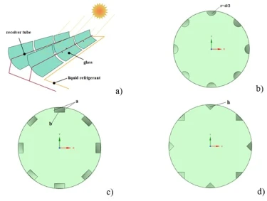
The purpose of this work is to numerically analyze the effect of the geometry of spiral axial fins with three different cross-sectional shapes (semicircular, rectangular and triangular) on heat transfer processes and hydrodynamic characteristics in pipes of a linear focusing solar collector (figure 1 b,c,e). The study is aimed at studying the behavior of the coolant at a Reynolds number of 5000, which corresponds to a turbulent flow regime. The simulation is performed using advanced computational methods implemented in the Ansys Fluent software, which allows detailed data to be obtained for analyzing and optimizing the design of heat exchange systems.
The results of this study have both scientific and practical significance. They allow us to deepen our understanding of the mechanisms of interaction of the geometric characteristics of the fins with the coolant, as well as provide recommendations on choosing the optimal configuration of the internal pipe elements to increase the efficiency of linear solar collectors. These findings can be useful for a wide range of tasks related to improving heat exchange equipment, reducing energy consumption, and increasing the efficiency of renewable energy systems [20-22].
Thus, the work is aimed at solving one of the urgent tasks of modern energy industry increasing the efficiency of using solar energy through optimizing the designs of heat transfer systems. The results obtained will contribute to the development of sustainable energy technologies and the implementation of global goals to reduce the carbon footprint and transition to a low-carbon economy.
The systems of parabolic grooved solar collectors shown in figure 1a are widely used due to their ability to concentrate solar radiation, ensuring high efficiency of heating the coolant with minimal heat losses. [23-27] These devices are based on the principle of focusing solar energy using a parabolic reflector that directs radiation to an absorbent tube, which makes them indispensable in the field of solar thermal energy. Parabolic collectors are used in hot water supply systems, steam generation processes and other tasks requiring a high temperature of the coolant. In this study, a parabolic grooved collector with a heat exchanger tube equipped with internal spiral fins was chosen as the object of modeling. The geometric parameters of the structure, including tube length, diameter, and rib shapes, are shown in detail in figure 1b-d. A three-dimensional formulation using the control volume method (FVM) in the Ansys Fluent software environment version 2024b was used for numerical analysis. All key parameters of the heat exchange tube, including length 𝐿=1000 mm, diameter 𝐷=32 mm, and pitch of the spiral fins 𝑃 = 125 mm, were taken into account to ensure high accuracy of calculations. The radii and sizes of the edges varied depending on their shape: for semicircular = 𝑑/2 = 2 mm, for rectangular a = b/2 = 2 mm, and for triangular - height h = 2 mm. The simulation was carried out at the initial temperature of the coolant inlet 𝑇=288 K and the Reynolds number 5000, which corresponds to the turbulent flow regime. To simplify calculations, the temperature of the outer wall of the tube was assumed to be constant and was 𝑇walls = 343 K. The results of numerical simulation have shown that the use of spiral fins inside the tube significantly improves the heat transfer characteristics. This is achieved by enhancing turbulent processes and creating vortex structures that increase the intensity of heat transfer. In addition, structures with different rib cross-sectional shapes exhibit different efficiencies: semicircular ribs ensure a stable distribution of turbulence, rectangular ribs contribute to more intense vortex flows, and triangular ribs create the most pronounced vortex structures. Thus, spiral fins are an effective means of intensifying heat transfer, which confirms their importance for improving the performance of parabolic solar collectors.

Figure 1. (a) Structural diagram of a parabolic solar collector, (b) internal spiral axial fins of semicircular cross-section, (c) internal spiral axial fins of rectangular cross-section, (d) internal spiral axial fins of triangular cross-section
 (1)
(1)
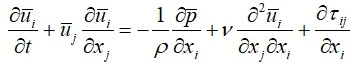
The equation of conservation of momentum, which describes the change in fluid velocity under the influence of external and internal forces:
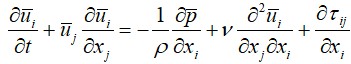 (2)
(2)
Where denotes components of the average velocity field,
denotes average pressure, ν denotes kinematic viscosity,
denotes components of the stress tensor, ρ denotes density.
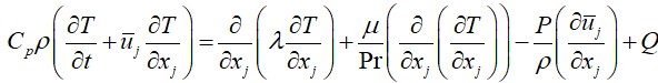
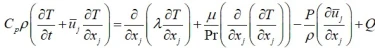
For a compressible fluid, the energy transfer equation takes into account changes in the internal energy of the fluid in response to changes in pressure and temperature. The formulation of the energy equation for a compressible fluid is as follows [14–19]:
 (3)
(3)
where ρ is the liquid density, С𝑝 is the specific heat capacity in constant pressure, 𝑇 is the temprature, 𝑡 is the time, 𝑢 is the velocity vector, 𝜆 is the coefficient of thermal conductivity, 𝜇 is the dynamic viscosity of the liquid, Pr is the Prandtl number (ratio of viscosity coefficient to thermal conductivity coefficient), 𝑃 is the pressure and 𝑄 is the heat source.
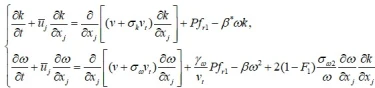
SST-RC (Shear Stress Transport with Recirculation Correction) is an improved version of the standard SST (Shear Stress Transport) model designed for more accurate modeling of turbulent flows, especially in areas with pronounced recirculation flows, such as areas of flow separation and flows with large pressure gradients. The main purpose of the SST-RC model is to improve the predictions of turbulent flow in areas with flow reconnection and near walls, where standard models can give significant errors. This modification preserves the structure of the standard SST model, but makes adjustments to the generating term P by multiplying it by the fr1 function, which takes into account the effect of recycling. This improvement allows for more accurate modeling of complex turbulent processes, such as separation of the flow and its reconnection, which is important for the correct description of such phenomena in engineering applications.
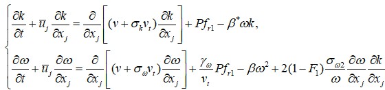 (4)
(4)
The SST-RC model is widely used in numerical modeling problems in the fields of aerodynamics, hydrodynamics, and heat transfer, especially in cases where standard models cannot predict complex turbulent phenomena. For example, it is effective in modeling flows in channels with turns, behind streamlined bodies, or in heat exchangers, where the processes of separation and reconnection of the flow are important [11].
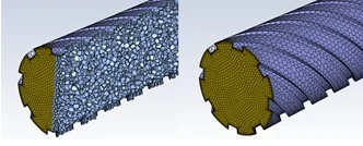
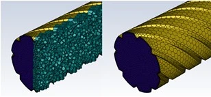
The generated grids for the proposed geometry are shown in figure 2.
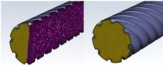
Figure 2. The grid under consideration for the proposed geometry. (a) internal helical axial ribs of semicircular section, (b) internal helical axial ribs of rectangular section, (c) internal helical axial ribs of triangular section
a)
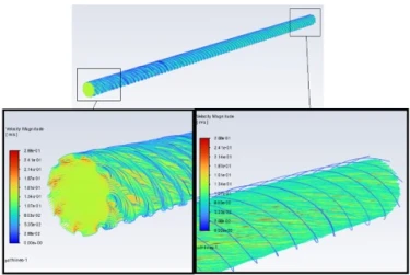
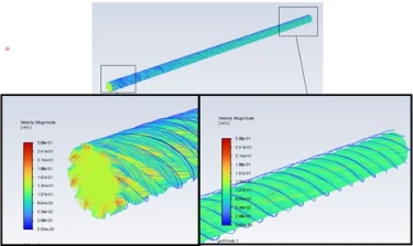
Figure 3 shows the changes in velocity isolines in the flow at the Reynolds number Re=5000. These isolines illustrate the velocity distribution at different points of the flow, reflecting the nature of the turbulent flow. At a given value of the Reynolds number, corresponding to a developed turbulent regime, the isolines show strong fluctuations and instabilities in the flow, characteristic of turbulent flows.
Changes are particularly noticeable in areas with high velocity gradients, such as recirculation zones or flow separation areas. These areas can significantly affect the heat exchange and hydrodynamic characteristics of the system, since turbulent vortices and mixing of the flow contribute to an increase in the intensity of heat exchange and an increase in the heat transfer coefficient.
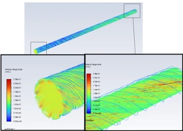
Figure 4 shows a streamline that shows the trajectory of liquid particles in a stream. Streamlines allow you to visualize the direction and nature of the flow movement, as well as help you understand its main features, such as the confluence area, separation zones, and recirculation flows. These lines are an important tool for analyzing turbulent and laminar flows, as they provide insight into how fluid movement depends on the geometry of a pipeline or channel, as well as on the strength and direction of external influences. In the case of turbulent flows, streamlines can have a complex structure, including vortices and local eddy currents, which can significantly affect the heat exchange process and hydrodynamic losses in the system.

Figure 3. The changes in velocity isolines at the Reynolds number Re=5000
a) Internal screw axial ribs of semicircular section; b) Internal screw axial ribs of rectangular cross section; c) Internal screw axial ribs of triangular cross section
a)

Figure 4. Velocity magnitude: a) Internal screw axial ribs of semicircular section; b) Internal screw axial ribs of rectangular cross section; c) Internal screw axial ribs of triangular cross section
a)
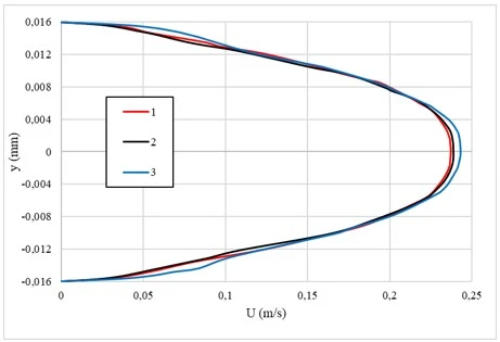
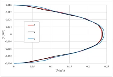
Figure 5. Comparative analysis of the flow velocity in the section z = 900 mm. Here, the internal helical axial ribs 1-semicircular, 2-rectangular, and 3-triangular in cross section
The pressure loss in the pipe is 35 Pa with a semicircular shape, 39,1 Pa with a rectangular shape and 43,5 Pa with a triangular shape of the inner screw axial ribs. These values indicate that as the geometry of the edges increases in complexity (from semicircular to triangular), pressure losses increase. This is due to the fact that more complex fin shapes, such as triangular ones, create more intense turbulent processes and flow resistance, which leads to increased pressure losses. At the same time, the semicircular shape, being less aggressive to the flow, causes less pressure loss, which makes it more effective in terms of flow resistance, but can reduce the intensity of heat exchange.
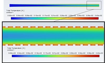
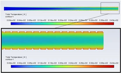
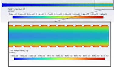
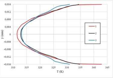
Figure 6 shows the change in the flow temperature in the area z=950 mm. From this figure, it can be seen that the flow temperature of the internal screw axial ribs of rectangular cross-section has increased compared to other ribs. This phenomenon is caused by increased turbulent processes caused by the geometry of the fins, which contributes to better mixing of the coolant.
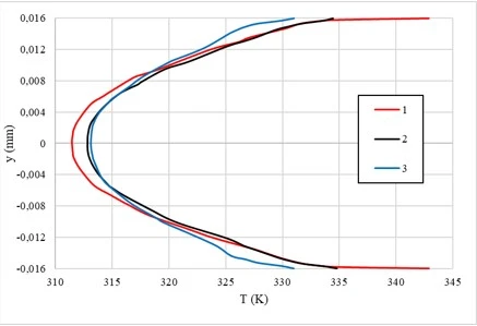
Figure 6. Temperature distribution in the 900 mm section. Here, the internal helical axial ribs 1 are semicircular, 2-rectangular, and 3-triangular in cross section
Internal screw axial ribs of rectangular cross-section create additional vortex structures that increase the intensity of heat exchange between the flow and the walls of the pipe. As a result, the coolant heats up faster, which leads to an increase in its temperature in this area. The above images show that the outlet water temperature is 331 K for the semicircular shape, 333 K for the rectangular shape, and 329 K for the triangular shape of the inner screw axial fins. These temperature values may indicate different heat transfer efficiencies for each rib geometry. The rectangular shape, with an outlet temperature of 333 K, can provide better flow contact with the heat exchange surface, which contributes to higher heat exchange. While the semicircular and triangular shapes of the fins show slightly lower temperatures, which may indicate their different hydrodynamic characteristics and the effects of turbulence in the flow.
In conclusion, a numerical study of the effect of various cross-sectional shapes of internal helical axial fins (semicircular, rectangular and triangular) on heat transfer and hydrodynamic characteristics of pipes of a linear focusing solar collector has shown the following results. Firstly, the shape of the fins has a significant effect on the temperature and flow rate. Thus, rectangular fins contribute to the most efficient increase in outlet temperature, which is associated with more intense turbulent processes and improved heat exchange. Semicircular fins show slightly better heat transfer results compared to triangular fins, despite some increased pressure losses. Secondly, an increase in the complexity of the shape of the ribs, such as triangular, leads to increased pressure losses. This is due to the increased flow resistance resulting from the more aggressive geometry of the fins, which increases turbulence and vortex structures. Thus, the results of the study confirm that the choice of the shape of the internal screw axial fins should be based on an optimal balance between heat transfer efficiency and acceptable pressure losses. This is important for the development of more efficient solar collectors and other heat exchange systems, where high performance is important with minimal energy costs to overcome pressure losses.
1 S.A. Berger, L. Talbot, L.S. Yao, Annu. Rev. Fluid Mech. 15 (1983) 461. http://dx.doi.org/10.1146/annurev.fl.15.010183.002333
2 M. Sheikholeslami, M. Gorji-Bandpy, D.D. Ganji, Renew. Sustain. Energy Rev. 49 (2015) 444. https://doi.org/10.1016/j.rser.2015.04.113
3 M.H. Esfe, S. Saedodin, S. Wongwises, D. Toghraie, J. Therm. Anal. Calorim. 119(3) (2015) 1817. http://dx.doi.org/10.1007/s10973-014-4328-8
4 M. Zaboli, S.S. Ajarostaghi, M. Noorbakhsh, M.A. Delavar, SN Appl. Sci. 1 (2019) 1387. https://doi.org/10.1007/s42452-019-1431-2
5 K. Kim, K.S. Lee, Int. J. Heat Mass Transf. 60 (2013) 505. http://dx.doi.org/10.1016/j.ijheatmasstransfer.2011.02.065
6 D. Gao, Y. Wang, Eur. Phys. J. Plus 135(11) 2020 921. http://dx.doi.org/10.1140/epjp/s13360-020-00929-0
7 A. Hobbi, K. Siddiqui, Int. J. Heat Mass Transf. 52(19-20) (2009) 4650. https://doi.org/10.1016/j.ijheatmasstransfer.2009.03.018
8 A. Nuntaphan, S. Vithayasai, N. Vorayos, N. Vorayos, T. Kiatsiriroat, Int. Commun. Heat Mass Transf. 37(3) (2010) 287. http://dx.doi.org/10.1016/j.icheatmasstransfer.2009.11.006
9 M. Zaboli, S.S. Mousavi Ajarostaghi, S. Saedodin, M. Saffari Pour, Applied Sciences 11(16) (2021) 7423. https://doi.org/10.3390/app11167423
10 Z.M. Malikov, A.A. Mirzoev, M. Madaliev, Journal of Computational Applied Mechanics 53(2) (2022) 282. http://dx.doi.org/10.25206/978-5-8149-3453-6-2022-192-202
11 Z.M. Malikov, M.E. Madaliev, D.P. Navruzov, K. Adilov, In AIP Conference Proceedings, AIP Publishing 2637(1) (2022) 040023. http://dx.doi.org/10.1063/5.0118473
12 M.Madaliev, E. Yunusaliev, A. Usmanov, N. Usmonova, K. Muxammadyoqubov, In E3S Web of Conferences, EDP Sciences (2023) 01011. https://doi.org/10.1051/e3sconf/202336501011
13 E. Madaliev, M. Madaliev, S. Raxmankulov, S. Raxmonkulova, In E3S Web of Conferences, EDP Sciences 452 (2023) 02012. . https://doi.org/10.1051/e3sconf/202345202012
14 M. Madaliev, J. Orzimatov, Z. Abdulkhaev, O. Esonov, M. Mirzaraximov, In BIO Web of Conferences, EDP Sciences 84 (2024) 02032. http://dx.doi.org/10.1051/bioconf/20248402032
15 B.A. Abdukarimov, A.A. Kuchkarov, Applied Solar Energy 58(1) (2022) 109. http://dx.doi.org/10.3103/S0003701X22010029
16 Z.M. Malikov, M.E. & Madaliev, Vestnik Tomskogo Gosudarstvennogo Universiteta Matematika i Mekhanika 71 (2021) 121. http://dx.doi.org/10.17223/19988621/71/10
17 B. Abdukarimov, S. O’tbosarov, A. Abdurazakov, E3S Web of Conferences, EDP Sciences 264 (2021) 01031. https://doi.org/10.1051/e3sconf/202126401031
18 N.R. Avezova, A.U. Vokhidov, D.U. Abdukhamidova, E.Y. Rakhimova, Applied Solar Energy (English translation of Geliotekhnika) this link is disabled 52(3) (2016) 197. http://dx.doi.org/10.3103/S0003701X1603004X
19 B.A. Abdukarimov, A.A. Kuchkarov, Applied Solar Energy (English translation of Geliotekhnika) 58(6) (2022) 847. http://dx.doi.org/10.3103/S0003701X22060020
20 K.Z. Yu, G.L. Ding, T.J. Chen, Int. J. Refrig. 31(3) (2008) 472. https://doi.org/10.1016/j.ijrefrig.2007.07.006
21 D. Liu, C. Wu, K. Linden, J. Ducoste, Appl. Math. Modell. 31(9) (2007) 1753. https://doi.org/10.1016/j.apm.2006.06.004
22 S. Anand, S. Kumar, Proceedings of the 48th National Conference on Fluid Mechanics and Fluid Power (FMFP) India (2021) 575. http://dx.doi.org/10.1007/978-981-19-6270-7_96
23 K. Bhagat, and Sandip K. Saha, Renewable energy 95 (2016) 323. https://doi.org/10.1016/j.renene.2016.04.018
24 Z.D. Cheng, Y.L. He, J. Xia, Y.B. Tao, International Communications in Heat and Mass Transfer 37(7) (2010) 782. http://dx.doi.org/10.1016/j.icheatmasstransfer.2010.05.002
25 A.A. Hachicha, Numerical modelling of a parabolic trough solar collector, Terrassa (2013). https://dx.doi.org/10.5821/dissertation-2117-95129
26 R. Buehler, S. Yang, and J.C. Ordonez, 2016 IEEE Conference on Technologies for Sustainability (SusTech) (2016). http://dx.doi.org/10.1109/SusTech.2016.7897145
27 M.A.A. Alfellag, Modeling and experimental investigation of parabolic trough solar collector, Florida (2014). http://dx.doi.org/10.13140/RG.2.2.24281.24166
A. Kuchkarov, B. Abdukarimov, Analysis of the effect of the cross-section of spiral fins in pipes of a linear focusing solar collector on heat transfer efficiency and hydrodynamic properties, UNEC J. Eng. Appl. Sci. 5(1) (2025) 16-25. https://doi.org/10.61640/ujeas.2025.0502
Anyone you share the following link with will be able to read this content:
This article is licensed under the Creative Commons Attribution ( CC BY 4.0 ) License, which permits unrestricted use, distribution, and reproduction in any medium, provided the original author and source are credited.


S.A. Berger, L. Talbot, L.S. Yao, Annu. Rev. Fluid Mech. 15 (1983) 461. http://dx.doi.org/10.1146/annurev.fl.15.010183.002333
M. Sheikholeslami, M. Gorji-Bandpy, D.D. Ganji, Renew. Sustain. Energy Rev. 49 (2015) 444. https://doi.org/10.1016/j.rser.2015.04.113
M.H. Esfe, S. Saedodin, S. Wongwises, D. Toghraie, J. Therm. Anal. Calorim. 119(3) (2015) 1817. http://dx.doi.org/10.1007/s10973-014-4328-8
M. Zaboli, S.S. Ajarostaghi, M. Noorbakhsh, M.A. Delavar, SN Appl. Sci. 1 (2019) 1387. https://doi.org/10.1007/s42452-019-1431-2
K. Kim, K.S. Lee, Int. J. Heat Mass Transf. 60 (2013) 505. http://dx.doi.org/10.1016/j.ijheatmasstransfer.2011.02.065
D. Gao, Y. Wang, Eur. Phys. J. Plus 135(11) 2020 921. http://dx.doi.org/10.1140/epjp/s13360-020-00929-0
A. Hobbi, K. Siddiqui, Int. J. Heat Mass Transf. 52(19-20) (2009) 4650. https://doi.org/10.1016/j.ijheatmasstransfer.2009.03.018
A. Nuntaphan, S. Vithayasai, N. Vorayos, N. Vorayos, T. Kiatsiriroat, Int. Commun. Heat Mass Transf. 37(3) (2010) 287. http://dx.doi.org/10.1016/j.icheatmasstransfer.2009.11.006
M. Zaboli, S.S. Mousavi Ajarostaghi, S. Saedodin, M. Saffari Pour, Applied Sciences 11(16) (2021) 7423. https://doi.org/10.3390/app11167423
Z.M. Malikov, A.A. Mirzoev, M. Madaliev, Journal of Computational Applied Mechanics 53(2) (2022) 282. http://dx.doi.org/10.25206/978-5-8149-3453-6-2022-192-202
Z.M. Malikov, M.E. Madaliev, D.P. Navruzov, K. Adilov, In AIP Conference Proceedings, AIP Publishing 2637(1) (2022) 040023. http://dx.doi.org/10.1063/5.0118473
M.Madaliev, E. Yunusaliev, A. Usmanov, N. Usmonova, K. Muxammadyoqubov, In E3S Web of Conferences, EDP Sciences (2023) 01011. https://doi.org/10.1051/e3sconf/202336501011
E. Madaliev, M. Madaliev, S. Raxmankulov, S. Raxmonkulova, In E3S Web of Conferences, EDP Sciences 452 (2023) 02012. . https://doi.org/10.1051/e3sconf/202345202012
M. Madaliev, J. Orzimatov, Z. Abdulkhaev, O. Esonov, M. Mirzaraximov, In BIO Web of Conferences, EDP Sciences 84 (2024) 02032. http://dx.doi.org/10.1051/bioconf/20248402032
B.A. Abdukarimov, A.A. Kuchkarov, Applied Solar Energy 58(1) (2022) 109. http://dx.doi.org/10.3103/S0003701X22010029
Z.M. Malikov, M.E. & Madaliev, Vestnik Tomskogo Gosudarstvennogo Universiteta Matematika i Mekhanika 71 (2021) 121. http://dx.doi.org/10.17223/19988621/71/10
B. Abdukarimov, S. O’tbosarov, A. Abdurazakov, E3S Web of Conferences, EDP Sciences 264 (2021) 01031. https://doi.org/10.1051/e3sconf/202126401031
N.R. Avezova, A.U. Vokhidov, D.U. Abdukhamidova, E.Y. Rakhimova, Applied Solar Energy (English translation of Geliotekhnika) this link is disabled 52(3) (2016) 197. http://dx.doi.org/10.3103/S0003701X1603004X
B.A. Abdukarimov, A.A. Kuchkarov, Applied Solar Energy (English translation of Geliotekhnika) 58(6) (2022) 847. http://dx.doi.org/10.3103/S0003701X22060020
K.Z. Yu, G.L. Ding, T.J. Chen, Int. J. Refrig. 31(3) (2008) 472. https://doi.org/10.1016/j.ijrefrig.2007.07.006
D. Liu, C. Wu, K. Linden, J. Ducoste, Appl. Math. Modell. 31(9) (2007) 1753. https://doi.org/10.1016/j.apm.2006.06.004
S. Anand, S. Kumar, Proceedings of the 48th National Conference on Fluid Mechanics and Fluid Power (FMFP) India (2021) 575. http://dx.doi.org/10.1007/978-981-19-6270-7_96
K. Bhagat, and Sandip K. Saha, Renewable energy 95 (2016) 323. https://doi.org/10.1016/j.renene.2016.04.018
Z.D. Cheng, Y.L. He, J. Xia, Y.B. Tao, International Communications in Heat and Mass Transfer 37(7) (2010) 782. http://dx.doi.org/10.1016/j.icheatmasstransfer.2010.05.002
A.A. Hachicha, Numerical modelling of a parabolic trough solar collector, Terrassa (2013). https://dx.doi.org/10.5821/dissertation-2117-95129
R. Buehler, S. Yang, and J.C. Ordonez, 2016 IEEE Conference on Technologies for Sustainability (SusTech) (2016). http://dx.doi.org/10.1109/SusTech.2016.7897145
M.A.A. Alfellag, Modeling and experimental investigation of parabolic trough solar collector, Florida (2014). http://dx.doi.org/10.13140/RG.2.2.24281.24166