UNEC Journal of Engineering and Applied Sciences Volume 6, No 1, pages 71-79 (2026) Cite this article, ![]() 170 https://doi.org/10.61640/ujeas.2026.0506
170 https://doi.org/10.61640/ujeas.2026.0506
Large-scale construction works have been launched in the Republic of Azerbaijan under the leadership of the Supreme Commander-in-Chief, Mr. President Ilham Aliyev, in connection with the Great Return to the lands liberated by our victorious army as a result of the 44-day Patriotic War from the 30-year occupation. To increase the level of employment of the population resettled in these territories and to provide the population with food at the expense of internal resources, as in other regions of our republic, large-scale construction and restoration works in the fields of land reclamation and water management are envisaged in the regions of the republic liberated from occupation [1].
As in other fields, newly constructed or rehabilitated irrigation canals and collector-drainage networks in our globally integrated country should also meet world standards. For this purpose, it is necessary to renew and improve the composition of the existing park of machines in construction-operating organizations of "Azerbaijan Amelioration and Water Management" OJSC with new machinery produced in foreign countries, as machines meeting world standards and modern requirements are required when rehabilitating and constructing irrigation canals and collector-drainage networks [2].
Therefore, carrying out research to determine the optimal composition of used machine fleets (full utilization of machine capacity), optimization, and selection of a convenient method of technical operation of machine units and complexes (reduction of downtime during machine operation) are important tasks of the day.
The development of non-oil fields, including agriculture, in the Republic of Azerbaijan, which is rapidly developing all spheres of its economy, is directly related to the solution to the problem of acquiring and maintaining land plots suitable for agriculture. This problem can be solved by the rehabilitation of existing irrigation and collector-drainage networks and the construction of new ones in the required areas [3].
It is known that the purpose of the construction of irrigation and collector-drainage networks is the delivery of irrigation water to the plots and the removal of excess water from the plots. Nowadays, irrigation water saving is at the center of attention all over the world. Therefore, prevention of water loss in irrigation canals is necessary. To prevent leaks in canals, measures are taken to create anti-leak covers on newly constructed and reconstructed earthen irrigation canals. One of such measures is laying concrete covers on the canals [4].
Leakage occurring in canals, water loss, and an increase in groundwater levels cause the salinization of adjacent territories. The conducted research shows that construction-operational organizations of Azerbaijan “Amelioration and Water Management” OJSC carry out a large volume of work in this direction. However, it is known from the analysis of the composition of the operating machinery park of OJSC that construction machines of general purpose are used in the performance of the mentioned works, as there are no canal-digging, canal-cleaning, concrete paving, or underground drainage-installation machines of special purpose in the machinery parks of OJSC.
Currently, the Central Mugan Collector Operation Department is working on the reconstruction of the Kyzylarkh irrigation canal in the Imishli district. Observations made at the construction site show that during operation, this earthen bed channel was overgrown with various vegetation and silted up, because of which its water-permeable capacity decreased. During the reconstruction of the canal, the canal water was blocked, and its bed was compacted and filled with layers of soil brought from outside (from the dams).
For many years of the past century, researchers sought such a cross-section of an earthen channel in which the resultant force acting on each soil particle would be identical at every point of the wetted perimeter. A solution to this problem can be found in studies [5,6]. However, in practice it is almost impossible to implement a structurally uniform cross-section of a channel.
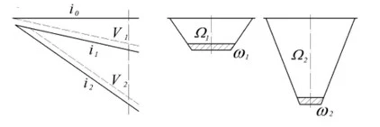
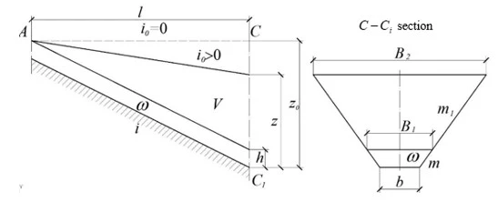
Figure 1. A longitudinal profile of two channels and the corresponding cross-sections of excavation at the end points
Let us turn to the idea expressed in [7,8] and explain its meaning using the diagram (figure 1). In figure 1, a longitudinal profile of two channels and the corresponding cross-sections of excavation at the end points are shown. The following notations are introduced in the figure:  is the slope of the terrain along which the channel route passes;
  is− the slope of the channel bed under uniform water flow;
  is the wetted cross-sectional area of flow;
  is the volume of soil lying above the water level in the channel that must be excavated in order to provide the channel bed with the required slope along its entire course. For greater clarity of the illustration, the terrain slope is taken to be zero. Further, we shall consider terrains where the surface slope satisfies the condition
  , if channel routes bypass sections of land with reverse slopes because of the considerable increase in the volume of earthworks.
With a large channel bed slope  , the water flow velocity
  U₂ is high, while the wetted cross-sectional area ω₂ at the considered section (for a constant discharge) is small, whereas the excavation area
  is large. Conversely, with a small bed slope
  , the wetted cross-sectional area ω₁ is large, and the excavation area
  is small. From the diagram it follows that the total excavation volume along the entire length of the channel depends on the sum of the areas
  , while the channel length itself depends on the bed slope. From this it follows that, under certain conditions, there exists a minimum volume of earthworks
  , which corresponds to the minimum value of the sum of areas
  . The corresponding bed slope of the channel can be defined as the optimal slope (figure 2).
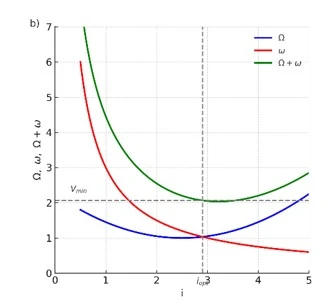
Figure 2. A diagram illustrating the existence of a minimum volume of earthworks at the optimal channel bed slope
Consider a channel with a composite trapezoidal cross-section, where the side slope coefficients within the wetted section are m and above the water surface are m₁ (figure 3). Suppose it is required to deliver a discharge Q from point A to point C, with the channel alignment being rectilinear and the wetted cross-sectional area equal to  . At point A, the water level in the channel is assumed to coincide with the ground surface. As is known, the channel bed slope equals tanα
 , where α is the angle of inclination of the channel bed relative to the horizontal line. The distance from point A to point C along the ground surface in a straight line is l. In this case, the length of the channel between the two points is equal to the length of the hypotenuse of the triangle:
  , since
  .
.
Thus, when determining the earthwork volume, the channel length can, without significant error, be taken as  . The water depth in the channel is denoted as
  . Since the water flow in the channel is uniform, the wetted cross-sectional area at point
  is equal to
  . The bottom width of the channel is
  , while the water surface width is
  . Considering the slopes of the bed and the ground surface, the excavation depth at point C becomes
  . The channel width at the top (at ground surface level) at its end section is
  .
.
The volume of earthworks for constructing a channel of length  is determined as the sum of the volumes of its individual geometric elements. As the first element, consider a prism with base area ω and height equal to the distance
  ; the excavation volume is
  . Next, consider two pyramids, each having as a base a right triangle with an area of
  . Let us express the excavation depth
  at point
  through the depth
  at the same point in the case where the ground surface is horizontal (see, figure 3), using the following identity:
  , where
  . In addition, note that
  . Using these transformations, the volume of soil in the two pyramids, whose bases are the above-mentioned triangles, is determined as:
  . It remains to determine the soil volume in the wedge located in the central part of the channel above the water level:
  .
.
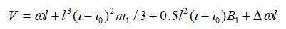
Thus, the volume of earthworks required for constructing a channel of length l is determined from the following relation:
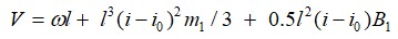 (1)
(1)
Let us express equation (1) in a dimensionless form:
 (2)
(2)
For trapezoidal cross-section channels, we have: the wetted cross-sectional area 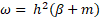 , and the water surface width at the top of the channel
 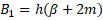 where
where 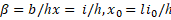 is the relative bottom width of the channel.
Let us denote:  then we obtain
 (3)
(3)
Let us perform the transformations on the left-hand side of equation (3) using hydraulic formulas:
 (4)
(4)
where  is water consumption in the canal and
  is water flow velocity in a canal;
  is the hydraulic radius;
  is the hydraulic friction coefficient;
  is the gravitational acceleration. We arrive at the following expression:
 (5)
(5)
where  is the reduced (dimensionless) volume of works:
 (6)
(6)
The actual volume of works is equal to:
 (7)
(7)
Let us substitute in (3) according to (7), divide the left and right sides of (7) by  , and obtain:
 (8)
(8)
It may turn out that the flow velocity of water in a canal of optimal dimensions exceeds the non-eroding velocity for the soil particles forming the canal bed. As an alternative, one may consider a canal lined with concrete within the wetted perimeter  . For further transformations, it is convenient to express the thickness of the lining h0 as a fraction of the flow depth
  :
: , where
  is the transition coefficient from the flow depth to the lining thickness. At the beginning of the calculations, this coefficient can be taken in the range of
  . At the end of the calculations, after the optimal parameters of the canal are found, the lining thickness may be adopted according to the current regulatory documents, and a correction can be introduced into the initial data to repeat the calculation with the corrected concrete lining thickness. Thus, at the beginning of the calculations, the area of the concrete lining – ω0 in the canal’s live cross-section can be determined from the following formula:
 (9)
(9)
According to construction standards, the concrete lining is laid on a preparation layer. The thickness of the preparation layer is determined as a fraction of the concrete lining thickness using the transition coefficient  from concrete works to special earthworks for preparation. At the initial stage of calculations, the transition coefficient can be taken as approximately
  . Once the thickness of the concrete lining has been determined, the thickness of the preparation layer should be adjusted in accordance with current regulations. Thus, at the beginning of the calculations, in the live cross-section of the flow, the area of the concrete lining with consideration of the preparation layer is taken according to the following relation:
 (10)
(10)
where 
In the calculations, the additional costs associated with creating a concrete lining in the channel can be considered in two ways. In the first method, the cost of the concrete lining and the preparation layer is added to the cost of the earthworks required for constructing the channel. In the second method, the volumes of the concrete lining and the preparation layer are added to the volume of the earthworks using generalized transition coefficients. The volume of earthworks for constructing a channel in an earthen bed with lining, according to formula (1), is determined as follows:
 (11)
(11)
Equation (11) differs from (1) by the presence of the fourth term  , which determines the dimensions of the lining with preparation. Let us transform this term using the relationship between the depth h and the area

we obtain
 (12)
(12)
After a certain period, digging of the bed of the new canal by a single bucket excavator on the route of the old canal started. The bed of the new canal was planned to be built up with concrete pavement. Construction of a concrete-lined canal is accompanied by digging the canal, leveling the slope and bottom of the canal (using a single-bucket excavator), assembling formwork on the bottom and slopes of the canal, and laying a layer of polyethylene on the bottom and slopes of the canal.
In the course of these works, operations on laying concrete coating on the working surfaces of the canal and filling of temperature joints are performed. Of the above operations, the operations on digging the channel and leveling of its slopes and bottom are performed by a single-bucket excavator, and the rest of the operations are performed manually. Ready-mix concrete is delivered to the site by a concrete mixer truck and fed into the channel by a special guide pipe.
It is known that irrigation water is supplied to land plots through temporary inter-farm, on-farm, and small-scale irrigation channels, differing in their sizes. Since the sizes of these canals are different, the equipment used for laying concrete lining in them must also be adapted to the different sizes. Integrated process mechanization is required to reduce the cost of work performed in the fields of land reclamation and water management, road construction and rehabilitation, and to reduce construction time by increasing productivity. To this end, various means of mechanization are used when laying concrete pavements in channels, depending on the size of the channel. With the introduction of such equipment, manual labor is completely eliminated, and work quality and productivity are improved. As an example, machines and equipments manufactured by the California-based company “Guntert & Zimmerman” can be cited [9]:
Towed and self-propelled pavers are used for concrete paving in channels up to 1.2 m deep [10]. The towed paver is designed for paving inside the finished channel; the paver is towed to a grader or loader. As they are quite light, they can be easily repositioned and pulled out of the canal. Because the canal bed is made according to the design dimensions, there is no need to automatically adjust their heights and forward directions.
The self-propelled compact concrete paver with profiling working element has two or four crawler tracks, depending on the size of the channel. The profiling working element is pulled out of the channel for repositioning and transportation. It is also equipped with automatic adjustment system of its height and forward direction. A conventional conveyor feeder is used to feed the concrete into the working element. A towable concrete paver is used for laying concrete pavements in precisely sized earthen bed channels. They have their own power unit and winch and are not towed.
The large towable paver cannot be lifted by a crane and pulled out of the canal due to its weight. At the front, this paver has a concrete distribution system consisting of a loading conveyor to ensure an even distribution of concrete. Concrete pavement placement in channels with a depth of 1.2–2.4 m is performed using the equipment.
The large, self-propelled, full-profile concrete paver is mounted on two to four crawler tracks. Its height position is automatically adjusted. The machine is also equipped with a loading conveyor, providing an even distribution of concrete in the front part.
The self-propelled concrete paver machine is used for the placement of pavement in distribution and secondary trunk channels. The tractor of the concrete paver machine includes cantilever stands, a power unit, a control system, removable stands, and two or four crawler tracks. The paver machine is equipped with vibrators and a concrete distribution system. To ensure an even distribution of the concrete mix when working in large channels, the loading hopper is equipped with a bucket or scraper conveyor. The concrete mix is poured directly into the hopper from the concrete mixer truck. Special construction is used to adapt small concrete paver machines to the dimensions of the canals. The working element has baffles, vibrators, sliding forms, and a back-running bridge that are installed to prevent the concrete mixture from flowing down slopes. The height and direction of travel of the machine is determined according to the planned surface. No additional equipment is required for the movement of the machine.
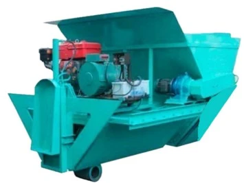
Concrete mixture compaction and surface smoothing is required to prevent depressions and cracks from forming and to remove noticeable stone parts during laying of concrete lining. Doing this process manually takes a lot of time. The XD-YQH1600 coating machine manufactured in the Republic of China is a mobile specialized electro-hydraulic construction technique that is widely used [11]. This machine draws, smoothes and compacts concrete cover along the entire perimeter of the canal in one go (figure 4).
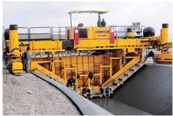
The machine places concrete pavement into a finished channel of a trapezoidal cross-section. Its front and back sides are made to match the exact cross-sectional profile of the channel. The manufacturer therefore designs and manufactures the working elements to match the cross-sectional profile of the channel. The machine is used in a completely safe manner. Since the machine is used in the field conditions, it comes with reliable and quality components. In operation, the machine compacts the concrete mix from the hopper after distributing it around the perimeter of the channel while pulling it through the finished channel. Compaction is carried out through a vibrator. Shock absorbers are used to prevent the whole machine from vibrating during compaction. The control system is a simple electrical circuit.When placing concrete pavements in large canals, a sliding form paver machine manufactured by the American company GOMACO is used (figure 5) [12]. GOMACO company equipment is manufactured to meet all operational safety requirements and operates reliably and trouble-free for many years. It is possible to lay a concrete cover in one walk using a trapezoidal sectional formwork, which can be adjusted according to the width, slope and depth of the channel. The sectional mold and front hopper are equipped with various attachments to change the slope and depth of the channel.
In order to coordinate all these transitions when working on the construction site, GOMACO engineers provided a series of diagrams with instructions for the width, slope and depth of the channel. The profile of the channel is excavated with excavators, and the chain trimmer mounted on the front of the GP-2600 paver is used to cut the protrusions on the surface of the channel.
Preventing water losses caused by seepage in earthen canals is of great importance in ensuring maximum water saving under global warming conditions. For this purpose, the application of concrete lining in earthen canals is considered more appropriate. Concrete lining not only minimizes seepage losses but also increases the durability of the insulation layer and ensures more stable hydraulic conditions. Before the placement of the concrete lining, canals are excavated in earthen beds. At this stage, the natural slope of the terrain must be considered, and the required longitudinal slope of the canal bed should be provided to ensure faster delivery of water to the fields. The excavation of soil is a labor-intensive process, and in this study, its details have been analyzed, and the conditions of optimality have been investigated. The research carried out shows that, at present, no special-purpose concrete paving machines are used for irrigation canals in our republic. However, the use of such machines would not only significantly reduce labor input and the cost of work but also improve the quality and productivity of the technological process of concrete lining in irrigation canals of various sizes.
1 V.T. Chow, Open-Channel Hydraulics, McGraw-Hill Book Company: New York (1959) 692 p.
2 W.H. Graf, Hydraulics of Sediment Transport, McGraw-Hill Book Company: New York (1970) 513 p.
3 M.A. Mikhalev, Yu.I. Chirikina, Proc. St. Petersburg State Technical University 475 (1998) 93.
4 M.A. Mikhalev, O.V. Obodova, VI All-Russian Hydrological Congress, St. Petersburg (2004) 32.
5 R. Kumar, A. Deshpande, J. Water Resour. Plan. Manag. 137(2) (2011) 155.
6 P. Jadhav, R. Thokal, M. Mane, H. Bhange, S. Kale, Int. J. Eng. Innov. Res. 3(6) (2014) 820.
7 J. Wang, G.B. Jiren, L. Zhang, China-Arab States Sci. Technol. Forum 9 (2020) 56.
8 L. Qingfu, International Journal of Civil Engineering 20(3) (2022) 245.
9 Q. Li, L. Guo, H. Zhou, Sustainability 14(13) (2022) 7663. https://doi.org/10.3390/su14137663
10 J.J. Li, X.L. He, B.L. Zhou, J. Coast. Res. (2019) 264.
11 H.L. Liu, D.H. Ma, C.M. Wang, X.Y. Liu, D. Wu, K.U.J. Khan, Bull. Eng. Geol. Environ. 80(11) (2021) 8397. https://doi.org/10.1007/s10064-021-02447-4
12 Q.F. Li, B.H. Wu, H.D. Zhou, Sustainability 14(15) (2022) 9202. https://doi.org/10.3390/su14159202
13 J. Wanyama, E. Bwambale, ISH J. Hydraul. Eng. 30(1) (2024) 7. https://doi.org/10.1080/09715010.2023.2245785
14 X.J. Fan, F. Ye, C.C. Pang, G.Y. Liu, X.H. Wang, L.R. Wang, J.F. Wei, Sci. Rep. 15(1) (2025) 43974. https://doi.org/10.1038/s41598-025-27749-5?urlappend=%3Futm_source%3Dresearchgate.net%26utm_medium%3Darticle
15 P. Gajbhiye, N. Vaidya, H. Erfan, D. Jain, M. Meenal, MethodsX 15 (2025) 103704. https://doi.org/10.1016/j.mex.2025.103704
A.F. Gasimov, Improvement of vehicle park composition used in the construction of concrete lined canals, UNEC J. Eng. Appl. Sci. 6(1) (2026) 71-79. https://doi.org/10.61640/ujeas.2026.0506
Anyone you share the following link with will be able to read this content:
This article is licensed under the Creative Commons Attribution ( CC BY 4.0 ) License, which permits unrestricted use, distribution, and reproduction in any medium, provided the original author and source are credited.
V.T. Chow, Open-Channel Hydraulics, McGraw-Hill Book Company: New York (1959) 692 p.
W.H. Graf, Hydraulics of Sediment Transport, McGraw-Hill Book Company: New York (1970) 513 p.
M.A. Mikhalev, Yu.I. Chirikina, Proc. St. Petersburg State Technical University 475 (1998) 93.
M.A. Mikhalev, O.V. Obodova, VI All-Russian Hydrological Congress, St. Petersburg (2004) 32.
R. Kumar, A. Deshpande, J. Water Resour. Plan. Manag. 137(2) (2011) 155.
P. Jadhav, R. Thokal, M. Mane, H. Bhange, S. Kale, Int. J. Eng. Innov. Res. 3(6) (2014) 820.
J. Wang, G.B. Jiren, L. Zhang, China-Arab States Sci. Technol. Forum 9 (2020) 56.
L. Qingfu, International Journal of Civil Engineering 20(3) (2022) 245.
Q. Li, L. Guo, H. Zhou, Sustainability 14(13) (2022) 7663. https://doi.org/10.3390/su14137663
J.J. Li, X.L. He, B.L. Zhou, J. Coast. Res. (2019) 264.
H.L. Liu, D.H. Ma, C.M. Wang, X.Y. Liu, D. Wu, K.U.J. Khan, Bull. Eng. Geol. Environ. 80(11) (2021) 8397. https://doi.org/10.1007/s10064-021-02447-4
Q.F. Li, B.H. Wu, H.D. Zhou, Sustainability 14(15) (2022) 9202. https://doi.org/10.3390/su14159202
J. Wanyama, E. Bwambale, ISH J. Hydraul. Eng. 30(1) (2024) 7. https://doi.org/10.1080/09715010.2023.2245785
X.J. Fan, F. Ye, C.C. Pang, G.Y. Liu, X.H. Wang, L.R. Wang, J.F. Wei, Sci. Rep. 15(1) (2025) 43974. https://doi.org/10.1038/s41598-025-27749-5?urlappend=%3Futm_source%3Dresearchgate.net%26utm_medium%3Darticle
P. Gajbhiye, N. Vaidya, H. Erfan, D. Jain, M. Meenal, MethodsX 15 (2025) 103704. https://doi.org/10.1016/j.mex.2025.103704