UNEC Journal of Engineering and Applied Sciences Volume 5, No 2, pages 75-87 (2025) Cite this article, ![]() 567 https://doi.org/10.61640/ujeas.2025.1206
567 https://doi.org/10.61640/ujeas.2025.1206
5G communication systems operate across an extensive portion of the radio spectrum, particularly within the millimetre-wave region. The FCC has allocated the 27.5–28.35 GHz band for 5G use, while the ITU identifies several broader ranges for global deployment, including 3.4–3.6 GHz, 5–6 GHz, 24.25–27.5 GHz, 37–40.5 GHz, and 66–76 GHz [1]. At these elevated frequencies, electromagnetic signals experience substantial free-space path loss and are easily obstructed, resulting in a reduced signal-to-interference-plus-noise ratio (SINR) [2]. To mitigate these effects, high-gain and highly directive antennas are essential for focusing energy toward intended directions. 5G New Radio (NR) divides its operating spectrum into Frequency Range 1 (FR1) below 6 GHz—covering many legacy LTE bands and Frequency Range 2 (FR2) above 24 GHz, which enables very high data throughput over shorter distances. Prominent 5G NR bands such as n78 (3.5 GHz), n79 (4.7 GHz), n41 (2.5 GHz), and n28 (700 MHz) are widely adopted across global networks [3].
Several frequency bands, including 3.4–3.8 GHz and 25.5–27.0 GHz, have also been allocated for preliminary 5G trials and deployment. As the latest generation following 1G through 4G, 5G establishes a highly flexible and interconnected communication environment capable of supporting massive numbers of devices with improved reliability and user experience [4]. The transition from 4G to 5G promises significant enhancements, with data rates rising from roughly 35 Mbps to more than 50 Mbps, and latency decreasing from nearly 50 ms to about 1 ms. Operating across both low-frequency (<6 GHz) and high-frequency (6–100 GHz) ranges, 5G systems rely heavily on antenna arrays due to their ability to deliver strong directivity, higher gain, and precise beam steering features crucial for modern wireless infrastructure, radar systems, satellites, and advanced 5G applications [5-6]. The primary advantage of antenna arrays lies in their capability for dynamic beamforming. By carefully adjusting the amplitude and phase of signals feeding each radiating element, the combined field can be shaped and steered electronically, allowing the antenna to track moving users or targets without mechanical rotation [7]. For millimetre-wave 5G systems, antennas must be extremely compact while maintaining high gain and narrow half-power beam widths (HPBW). The array proposed in this work leverages phase-controlled multiport excitation to steer the beam and manage the radiation direction effectively, an essential requirement given the propagation challenges associated with high frequency signals [8-9].
This research aims to design an efficient antenna operating in the 28 GHz band allocated for 5G GSM services by ITU standards. The proposed structure utilizes low-loss substrate materials and maintains a compact footprint while supporting multi-directional signal reception through a multiport configuration. Phase differences across the feeding ports are optimized to generate a narrow, highly directive beam with a gain exceeding 10 dB. The fundamental radiating element is a compact 2.95 × 2.95 mm² patch tailored for 28 GHz operation. Due to its small size, a transformer-coupled feed mechanism is adopted to achieve efficient excitation and support multi-beam radiation. The initial dual-port orthogonal transformer-fed design is expanded into two-element and four-element configurations, culminating in a five-element array with eight input ports. The central element is parasitically excited to enhance boresight directivity. Beam orientation is precisely controlled by adjusting input phase differences, enabling highly directive radiation at desired angles. Comprehensive optimization and experimental validation including comparison of measured and simulated return loss confirms the robustness and effectiveness of the proposed antenna system.
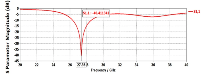
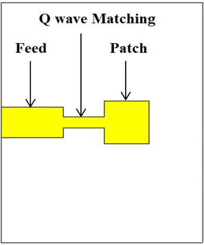
The design of the antenna array begins with the creation of a single radiating patch element, which subsequently serves as the foundational unit for constructing the complete array. This patch is excited through a microstrip feed line incorporating a quarter-wave impedance transformer to ensure proper matching. As shown in figure 1, the radiating element is a square patch measuring 2.95 mm × 2.95 mm. The antenna is fabricated on a Rogers RT5880LZ substrate, selected for its low permittivity value of 1.96 and thickness of 1.27 mm, and is optimized to operate at the target frequency of 28 GHz. The quarter-wave transformer is dimensioned at 0.72 mm × 2.7 mm, whereas the feed line length and width are 2.1 mm × 4.1 mm. Full-wave simulations of the single-port configuration were performed, and the resulting reflection coefficient (S11), shown in figure 2, indicates an initial resonance at 27.36 GHz with a minimum S11 of –40.41 dB, demonstrating excellent impedance matching.
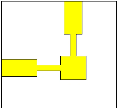
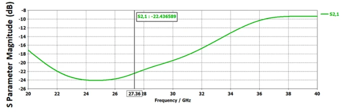
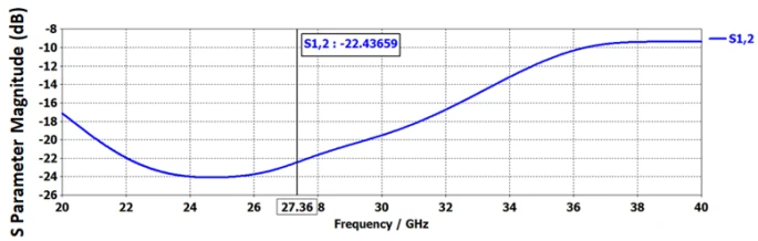
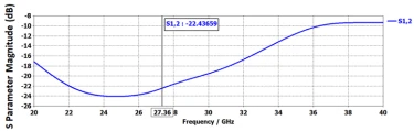
To enable the formation of multiple radiation beams, an optimized orthogonal feeding arrangement is employed. In this configuration, the patch is energized through two perpendicular feed ports, which allows the surface current distribution to be altered depending on the active port, as illustrated in figure 3. Ensuring low mutual coupling between these orthogonal ports is crucial for independent beam control. As shown in figure 4, the simulated S12 and S21 responses are identical, with both achieving –22.43 dB at 27.36 GHz. This low coupling level results from the orthogonal placement of the feeds, confirming that the two ports function independently with minimal interference.
 (1)
(1)
 (2)
(2)
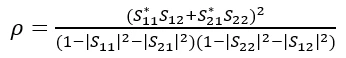
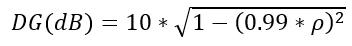
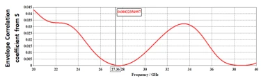
The correlation coefficient (ρ) and diversity gain between the two feeding ports are evaluated using the expressions provided in equations 1 and 2. Using these formulations, the calculated correlation coefficient is 0, while the diversity gain is 9.99 dB. The simulated variation of these parameters across the operating band is presented in figure 5. At the resonance frequency of 27.36 GHz, the correlation coefficient remains extremely low, and the diversity gain approaches the ideal value of 10 dB. These results confirm that the two ports exhibit minimal correlation and operate effectively as independent channels.
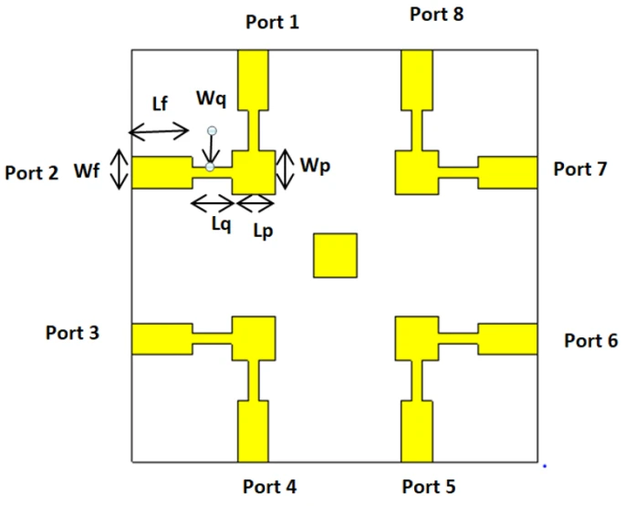
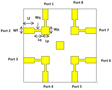
The finalized configuration of the five-element antenna array, incorporating a centrally positioned patch, is presented in gigure 6. In this arrangement, the central element is not directly fed but instead energized through parasitic coupling from the surrounding four patches, enhancing the strength and focus of the main radiation beam. The overall antenna structure maintains a compact footprint of 27.7 × 27.7 × 1.27 mm³, making it significantly smaller than many previously reported designs. All key geometric and structural parameters of the array are summarized in table 1.
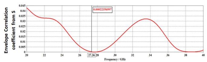
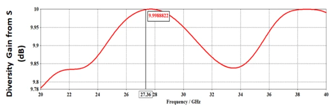
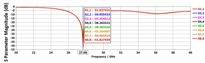
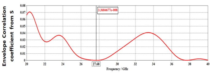
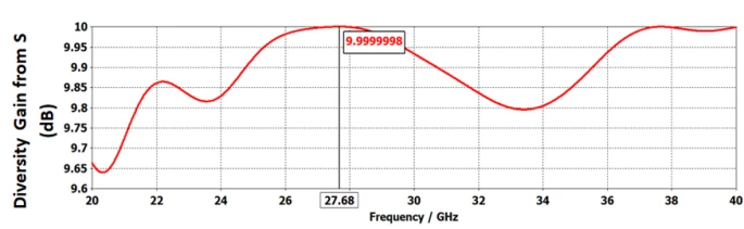
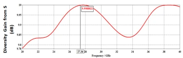
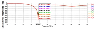
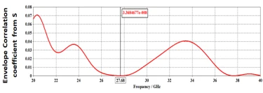
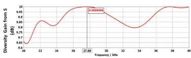
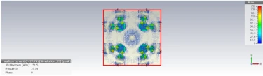
The simulated performance of the proposed antenna array in terms of return loss and correlation coefficient is presented in figure7 and figure 8, respectively. At the resonant frequency of 27.68 GHz, the array achieves an excellent return loss of –51.8 dB, while the correlation coefficient between the feeding ports is evaluated as zero, indicating complete independence between the ports. The corresponding diversity gain at this frequency is 9.99 dB, as depicted in figure 9. The surface current distribution illustrated in figure 10 shows that when all ports are excited with an identical phase (0° shift), the currents on the radiating patches are directed toward the central element, demonstrating effective multi-port excitation and confirming the intended array behavior.
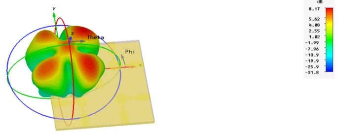
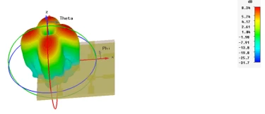
The optimized antenna array features five radiating patches powered through eight feeding ports, allowing flexible beam formation through controlled phase variation among the input signals. By adjusting the phase differences applied to these ports, the array can generate multiple radiation beams oriented in different directions. Depending on the selected phase configuration, the primary radiation can split into two, three, four, or even five distinct beams. The optimized outcomes for each case are illustrated using 3D radiation patterns and corresponding polar plots.
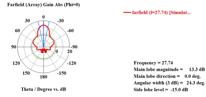
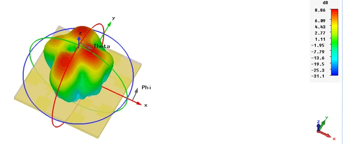
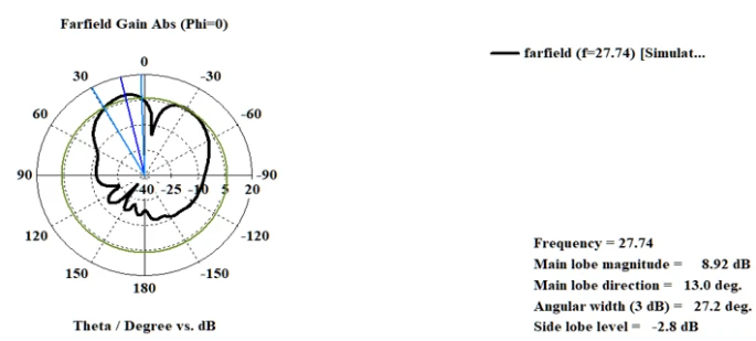
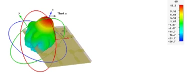
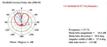
Case 1: In the first scenario, where a phase increment of 45° is applied across the feeding ports, the array produces a single, well-defined radiation beam, as depicted in figure 11.
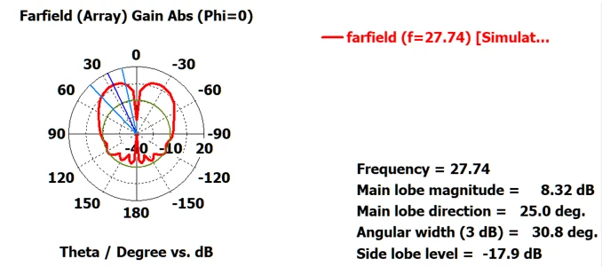
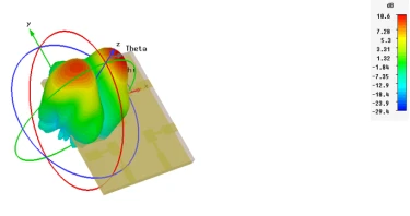
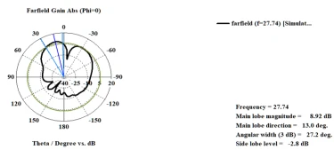
Case 2: When a phase shift of 110° is applied sequentially across the feeding ports, the antenna array generates two distinct radiation beams. This phase configuration effectively splits the main lobe into a dual-beam pattern, as illustrated in figure 12, demonstrating the array’s ability to support multi-directional beam formation.
Case 3: In this configuration, a 180° phase shift is introduced between the two ports of each individual patch, while maintaining an out-of-phase condition of 45° between adjacent patches. Under this combined phase arrangement, the antenna array produces three distinct radiation beams, as illustrated in figure 13. This result confirms the array’s capability to achieve controlled multi-beam operation through tailored intra-element and inter-element phase variations.
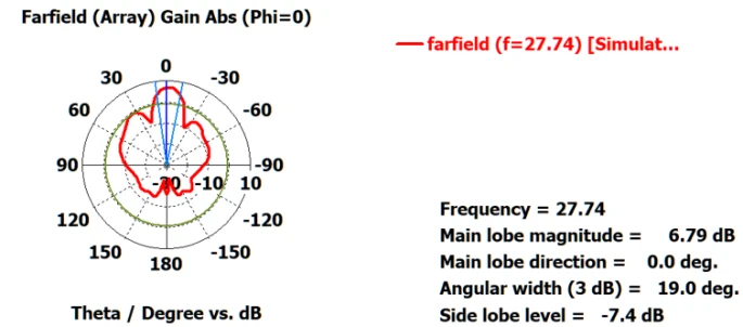
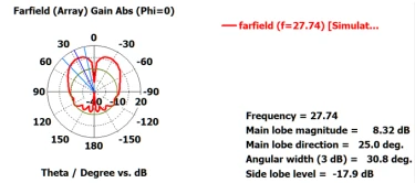
Case 4: When a uniform phase shift of 90° is applied across all feeding ports, the antenna array produces four distinct radiation beams. This phase configuration enables the main lobe to split into four symmetrical directions, forming a well-defined quad-beam pattern, as illustrated in figure 14.
Case 5: By applying a phase shift of 140° sequentially across the feeding ports, the antenna array produces five distinct radiation beams. This configuration results in a well-defined five-beam pattern, as depicted in figure 15, demonstrating the array’s capability to support wide-angle multi-beam radiation through appropriate phase control.
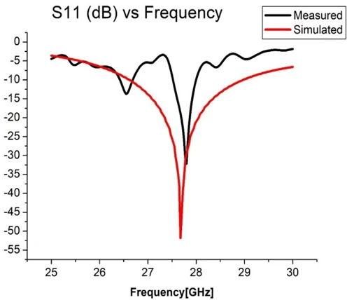
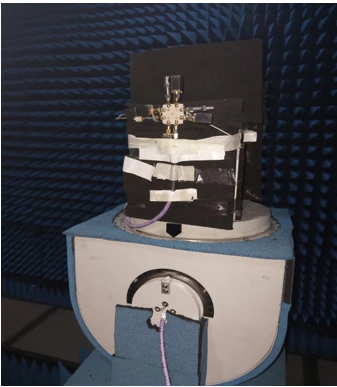
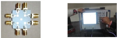
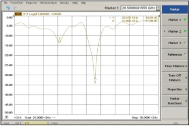
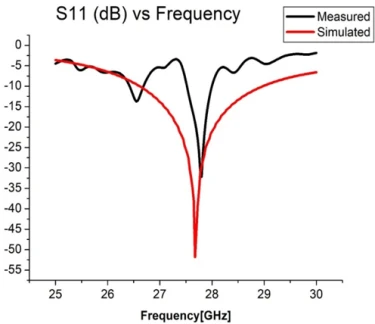
The finalized five-element patch array was fabricated on a Rogers RT5880LZ substrate (εr = 1.96) and experimentally characterized using a Rohde & Schwarz ZVA 40 Vector Network Analyzer, as shown in figure 16. The measured S11 response, presented in figure 17, exhibits a minimum at 27.8 GHz. A comparison of simulated and measured return loss results is illustrated in figure 18. The simulated design achieves an optimal resonance at 27.6 GHz, while the fabricated prototype resonates closely at 27.8 GHz. This close agreement between both results confirms the accuracy of the design approach and validates the overall performance of the proposed antenna array.
The finalized eight-port configuration shown in figure 6 was fabricated as illustrated in figure 16. For measurement, only a single port (Port 1) was excited while all remaining ports were terminated with matched loads. The radiation pattern of this setup was evaluated inside an anechoic chamber capable of supporting measurements up to 70 GHz, as depicted in figure 19.
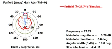
Figure 20 presents the comparison between the simulated and measured radiation patterns. The measurements were recorded in 5 degree increments over the full 0–360° range at the operating frequency of 27.7 GHz. The resulting curves show a close agreement between the measured data and the simulated predictions.
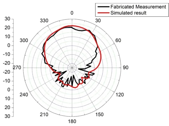
Figure 20. Comparison of Radiation patterns of fabricated design with simulated result
This work has demonstrated the complete development and verification of a compact multi-beam microstrip patch array featuring five radiating elements and eight excitation ports. Through the application of tailored phase configurations at the inputs, the array successfully produces one to five independent beams, enabling flexible coverage and the capability to receive signals from diverse propagation paths which is an essential feature for modern 5G systems. While the formation of multiple beams leads to a modest reduction in gain due to power being shared among various directions, the antenna’s overall performance remains robust and well suited for realistic multi-path wireless scenarios.
1 M.Y. Muhsin, Z.S. Muqdad, A.H. Sahar, Z.F. Mohammad, H. Al-Saedi, Journal of Telecommunications and Information Technology 99(1) (2025) 67. https://doi.org/10.26636/jtit.2025.1.1951
2 D.M. Pozar, Microwave Engineering, John Wiley & Sons (2011) 736p.
3 N.K. Mallat, M. Ishtiaq, A.U. Rehman, A. Iqbal, IETE Journal of Research 68(4) (2020) 2522. https://doi.org/10.1080/03772063.2020.1714489
4 R. Dangi, P. Lalwani, G. Choudhary, I. You, G. Pau, Sensors 22 (2022) 26. https://doi.org/10.3390/s22010026
5 S. Fulton III, ZDNet (2021). Available at: https://www.zdnet.com/article/what-is-5g-the-business-guide-to-next-generation-wireless-technology/
6 5G-Enabled Internet of Things, CRC Press (2019) 42p.
7 M. Bello, 5G Network: Expectation vs. Reality, Thesis, University of Wolverhampton (2021). https://doi.org/10.13140/RG.2.2.34227.14887
8 B. Bordel, R. Alcarria, T. Robles, Expert Systems 42(1) (2025) e13369. https://doi.org/10.1111/exsy.13369
9 Md.S. Rana, T.A. Fahim, S.B. Rana, R. Mahbub, Md.M. Rahman, TELKOMNIKA 21(5) (2023) 957. https://doi.org/10.11591/ijeecs.v32.i2.pp828-837
H. Nigam, M. Mathur, Multi-beam formation using a parasitic patch integrated microstrip array for 5G communications , UNEC J. Eng. Appl. Sci. 5(2) (2025) 75-87. https://doi.org/10.61640/ujeas.2025.1206
Anyone you share the following link with will be able to read this content:
This article is licensed under the Creative Commons Attribution ( CC BY 4.0 ) License, which permits unrestricted use, distribution, and reproduction in any medium, provided the original author and source are credited.


M.Y. Muhsin, Z.S. Muqdad, A.H. Sahar, Z.F. Mohammad, H. Al-Saedi, Journal of Telecommunications and Information Technology 99(1) (2025) 67. https://doi.org/10.26636/jtit.2025.1.1951
D.M. Pozar, Microwave Engineering, John Wiley & Sons (2011) 736p.
N.K. Mallat, M. Ishtiaq, A.U. Rehman, A. Iqbal, IETE Journal of Research 68(4) (2020) 2522. https://doi.org/10.1080/03772063.2020.1714489
R. Dangi, P. Lalwani, G. Choudhary, I. You, G. Pau, Sensors 22 (2022) 26. https://doi.org/10.3390/s22010026
S. Fulton III, ZDNet (2021). Available at: https://www.zdnet.com/article/what-is-5g-the-business-guide-to-next-generation-wireless-technology/
5G-Enabled Internet of Things, CRC Press (2019) 42p.
M. Bello, 5G Network: Expectation vs. Reality, Thesis, University of Wolverhampton (2021). https://doi.org/10.13140/RG.2.2.34227.14887
B. Bordel, R. Alcarria, T. Robles, Expert Systems 42(1) (2025) e13369. https://doi.org/10.1111/exsy.13369
Md.S. Rana, T.A. Fahim, S.B. Rana, R. Mahbub, Md.M. Rahman, TELKOMNIKA 21(5) (2023) 957. https://doi.org/10.11591/ijeecs.v32.i2.pp828-837