UNEC Journal of Engineering and Applied Sciences Volume 6, No 1, pages 39-58 (2026) Cite this article, ![]() 266 https://doi.org/10.61640/ujeas.2026.0504
266 https://doi.org/10.61640/ujeas.2026.0504
Solar thermal technologies are increasingly important for decarbonising electricity generation, industrial process heat, district heating, water treatment and hybrid renewable-energy systems. Among concentrating solar thermal technologies, parabolic trough collectors (PTCs) remain one of the most technically mature and commercially relevant options because of their relatively simple optical configuration, established receiver design, compatibility with thermal storage and suitability for medium- to high-temperature heat delivery [1–5]. In a PTC, direct normal irradiance is concentrated by a parabolic mirror onto a linear absorber tube located along the focal line. A heat-transfer fluid (HTF) circulates inside the receiver and transports the absorbed thermal energy to a power block, thermal storage system or process-heat application. One of the key operational parameters in PTC systems is the volumetric flow rate. A higher flow rate usually enhances the convective heat-transfer process inside the absorber tube, decreases the temperature difference between the absorber surface and the working fluid, suppresses excessive local heating and may contribute to lower heat losses from the receiver [11–14]. On the other hand, increasing the flow rate leads to higher fluid velocity, which intensifies frictional effects, raises the pressure drop and increases the pumping-power requirement. As a result, a thermo-hydraulic compromise emerges: the operating condition that provides the maximum thermal energy gain does not necessarily correspond to the maximum net energy output once the power consumed for fluid circulation is taken into account [15–18].
In this regard, D.Y. Jalilov et al. investigated the influence of volumetric flow-rate variation on pressure drop and pumping power in parabolic trough collectors. Their study demonstrated that hydraulic losses become more pronounced with increasing flow rate. The reported results indicate that optimisation of the flow regime should not rely solely on heat-transfer improvement, but must also consider the associated pressure-drop and pumping-power penalties caused by intensified circulation. This consideration is especially important in large-scale solar collector fields, where even relatively small increases in pumping demand may noticeably influence auxiliary energy consumption, operating expenses and the overall system efficiency.
The nature of this thermo-hydraulic balance is also highly dependent on the properties of the selected heat-transfer fluid.Commercial synthetic oils and silicone-based fluids, including Therminol VP-1, Therminol 66, Therminol 68, Therminol 59, Therminol 55, Therminol XP, Therminol D-12 and Syltherm 800, are widely used or considered in solar thermal and industrial heat-transfer systems because of their thermal stability, predictable property ranges and industrial availability [19–22]. However, these fluids differ substantially in density, heat capacity, dynamic viscosity, thermal conductivity, vapour pressure and recommended operating-temperature range. A fluid with favourable heat capacity may still be unattractive if its viscosity produces a large pumping-power penalty. Conversely, a fluid with low viscosity may reduce hydraulic losses but may require a higher mass-flow rate to deliver the same thermal output. Consequently, a fair comparison of HTFs requires simultaneous treatment of thermal performance, pressure drop and auxiliary pumping energy [23–26].
Early and classical PTC modelling studies established the fundamental energy-balance and receiver heat-loss formulations. The SEGS LS-2 experimental dataset reported by Dudley et al. [1] remains one of the most widely used benchmarks for validating parabolic trough receiver models. Forristall [2] developed a detailed heat-transfer model of a parabolic trough receiver and demonstrated the importance of accurately representing receiver heat losses, absorber temperature and fluid-side convection. Odeh et al. [3] modelled parabolic trough direct steam generation collectors and showed that receiver thermal behaviour is strongly affected by optical and operating conditions. Kalogirou [4] and Fernández-García et al. [5] also reviewed the progress and practical applications of solar thermal collectors and parabolic trough systems, emphasizing their technological advancement and broad range of applications. These studies provide a strong foundation for thermal modelling, but the hydraulic side of collector operation is often treated as a secondary consideration.
More recent research has focused on thermal enhancement through nanofluids, absorber modifications, inserts, turbulators and advanced receiver configurations [27–34]. Bellos and Tzivanidis [24, 25] reviewed and analysed the role of working fluids in concentrating solar thermal collectors and showed that fluid selection can substantially affect the thermal behaviour of PTC systems. Bellos et al. [26] also demonstrated that multi-criteria evaluation is necessary when receiver modifications or internal enhancements are used, because heat-transfer improvement may be accompanied by additional hydraulic losses. Mwesigye, Bello-Ochende and Meyer [14,15] investigated entropy generation and heat-transfer enhancement in parabolic trough receivers and showed that techniques improving thermal performance may also increase frictional irreversibility. Therefore, enhancement should be assessed not only through the heat-transfer coefficient or Nusselt number, but also through the net energetic and exergetic benefit after pumping losses are included. In this context, thermal-hydraulic performance evaluation becomes more meaningful than thermal efficiency alone.
Exergy analysis and entropy-generation minimisation provide additional insight into the quality of solar thermal conversion. Kalogirou [35] showed that exergy analysis is essential for evaluating solar thermal collectors because thermal efficiency alone cannot describe the useful work potential of the collected heat. Ndukwu et al. [36] reviewed exergy-based assessments of solar thermal systems and emphasised that exergy indicators provide a more realistic measure of thermodynamic performance than energy efficiency alone. Mostafizur et al. [37] further demonstrated, using solar collector systems with different working fluids, that energy and exergy efficiencies may lead to different interpretations of system performance. Therefore, in the present study, exergy efficiency is used as a complementary indicator to net useful power rather than as a replacement for thermal-hydraulic optimisation.
Entropy-generation analysis further separates irreversibilities associated with finite-temperature heat transfer from those associated with fluid friction. Mwesigye et al. [38] numerically investigated entropy generation in parabolic trough receivers and showed that both heat-transfer irreversibility and fluid-friction irreversibility must be considered when evaluating receiver performance. Bejan [9,40] established the theoretical basis for entropy-generation minimisation as a method for thermodynamic optimisation, while more recent solar-collector studies have applied this concept to evaluate irreversibilities in different receiver and working-fluid configurations [39,41]. These studies indicate that an optimum flow rate exists because low flow rates intensify heat-transfer irreversibility, whereas excessive flow rates increase frictional irreversibility through higher pressure drop.
Although the above studies provide important thermal, hydraulic and exergetic insights, several gaps remain for practical PTC flow-rate optimisation. First, many previous studies evaluated thermal efficiency, pressure drop, pumping power or exergy as separate indicators, whereas real collector operation requires their coupled interpretation. Second, although Jalilov et al. [42] highlighted the importance of volumetric-flow-rate adjustment for pressure drop and pumping power, the integration of this hydraulic penalty with net useful power, exergy efficiency and entropy-generation indicators still requires further development. Third, comparative studies of several commercial Therminol-series and silicone-based fluids under identical LS-2 geometry, identical boundary conditions and a unified optimisation objective remain limited. Finally, optimisation studies frequently report the flow rate that maximises useful heat gain, but they do not always distinguish it from the flow rate that maximises net useful power after subtracting pumping-power consumption.
The present study addresses these gaps by developing an integrated thermal-hydraulic and exergy-based optimisation framework for volumetric flow-rate selection in an LS-2 parabolic trough collector. The novelty of the work is not the use of standard heat-transfer and friction correlations alone, but their integration into a unified decision framework that couples receiver energy balance, internal convection, pressure drop, pumping power, net useful power, exergy efficiency and entropy-generation behaviour. This structure allows the optimum volumetric flow rate to be interpreted as a physically meaningful balance between thermal gain and hydraulic penalty.
The objectives of this study are therefore to: (i) model the thermal and hydraulic behaviour of an LS-2 parabolic trough collector using temperature-dependent HTF properties; (ii) determine the optimum volumetric flow rate for eight commercial HTFs over a wide inlet-temperature range; (iii) quantify the competition between useful heat gain and pumping-power penalty; (iv) introduce exergy and entropy-generation indicators to interpret thermal and hydraulic irreversibilities; (v) assess the sensitivity of the optimum flow-rate behaviour to operating and numerical parameters; and (vi) translate the results into engineering recommendations for heat-transfer-fluid selection and temperature-dependent flow-rate control.
Nomenclature
Subscripts: amb - ambient; f - fluid; fm - mean fluid; in - inlet; out - outlet; r - receiver; s - solar.
2.1. Physical model and collector configuration
The system considered in this study is an LS-2 parabolic trough collector module fitted with an evacuated receiver tube. The collector assembly includes a parabolic reflector, an absorber tube, a surrounding glass envelope and a solar tracking mechanism. Incident direct solar radiation is concentrated by the parabolic mirror onto the receiver surface. The selective coating on the absorber transforms the concentrated solar energy into thermal energy, which is then transferred to the heat-transfer fluid (HTF) circulating through the tube. The glass cover minimizes convective heat losses to the surroundings and contributes to preserving the thermal efficiency of the receiver.
The LS-2 collector was selected because it is a widely used benchmark geometry in PTC modelling and validation studies. The main parameters used in this work are: collector width 5.0 m, collector length 7.8 m, aperture area 39.0 m², focal distance 1.71 m, concentration ratio 22.74, receiver inner diameter 66 mm, receiver outer diameter 70 mm, cover inner diameter 109 mm, cover outer diameter 115 mm, absorber absorptance 0.96, cover transmittance 0.95, mirror reflectance 0.83, intercept factor 0.99, receiver emittance 0.20, cover emittance 0.90 and maximum optical efficiency 0.75. The incidence angle was taken as 0° in the baseline case, corresponding to ideal tracking and an incidence-angle modifier equal to unity. This assumption isolates the influence of HTF properties and volumetric flow rate from optical misalignment effects.
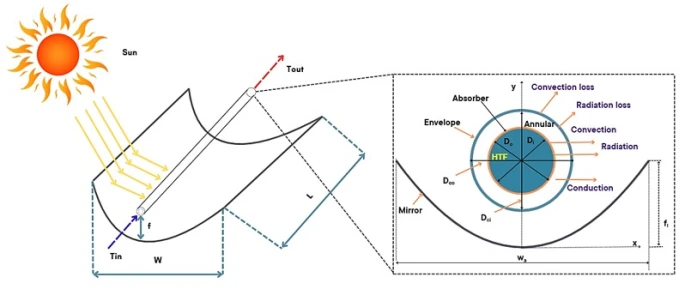
Figure 1. Physical model of the LS-2 parabolic trough collector and receiver heat-transfer scheme
2.2. Optical and receiver energy-balance model
The thermal behaviour of the parabolic trough collector was described using a one-dimensional steady-state energy-balance model developed for the receiver-fluid control volume. The model accounts for conversion of direct beam solar radiation into absorbed heat at the receiver surface, heat transfer from the absorber wall to the circulating HTF and thermal losses from the receiver assembly to the surrounding environment. The quasi-steady assumption is appropriate for comparative collector performance evaluation when changes in solar irradiance and ambient conditions occur over a longer time scale than the residence time of the fluid inside the absorber tube.
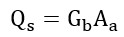
The solar power incident on the collector aperture is [1]:
where  is the direct beam solar irradiance and
  is the aperture area. Only part of this radiation is transferred optically to the absorber tube. The absorbed solar power is therefore:
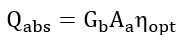
where  is the optical efficiency of the concentrator-receiver system. It is calculated as:
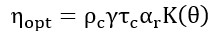
where  is the mirror reflectance,
  is the intercept factor,
  is the glass-cover transmittance,
  is the absorber absorptance and
  is the incidence-angle modifier. For the baseline calculations,
  , corresponding to normal incidence.
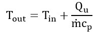
The useful thermal energy transferred to the fluid is calculated from the fluid-side energy balance:
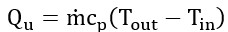
where  is the mass-flow rate,
  is the specific heat capacity and
  and
and  are the inlet and outlet fluid temperatures. The mass-flow rate is related to volumetric flow rate by:

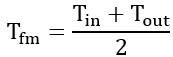
Since the properties of commercial HTFs are temperature-dependent,  ,
,  ,
,  and
and  were evaluated at the mean bulk-fluid temperature:
The receiver energy balance is expressed as:

or:
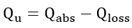
where  is the total heat loss from the receiver assembly to the environment. This loss includes radiative exchange between absorber and glass envelope, radiative exchange between glass envelope and sky and convective heat transfer from the outer glass surface to the ambient air. In compact engineering form, the total heat loss can be represented as:
where  is the overall receiver heat-loss coefficient,
  is the receiver surface area,
  is the absorber surface temperature and
  is the ambient temperature. The coefficient
  represents the coupled thermal-resistance network between absorber, glass envelope and ambient environment.
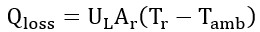
The heat transfer from absorber wall to fluid is:
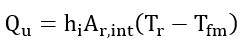
Therefore, the receiver temperature can be estimated as:
This equation provides the main coupling between energy balance and hydraulic behaviour. A low volumetric flow rate reduces hI , increases the absorber-to-fluid temperature difference and intensifies receiver heat losses. A higher flow rate enhances internal convection and decreases absorber temperature, but this improvement must be balanced against the pumping-power penalty.
The fluid outlet temperature is obtained as:
The gross collector thermal efficiency is:
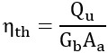
However, thermal efficiency alone does not represent the real useful output of the collector loop because auxiliary pumping energy is required. Therefore, the heat gain calculated in this section is coupled with the hydraulic model in Section 2.3 and with the net useful-energy objective in Section 2.4.
The main assumptions of the energy-balance model are: quasi-steady-state operation, one-dimensional axial heat transfer, incompressible fluid flow, temperature-dependent fluid properties evaluated at the mean bulk temperature, circumferentially averaged absorber temperature and constant optical properties over the investigated operating range. These assumptions provide a balance between physical fidelity and computational practicality for comparative optimisation of commercial HTFs.
2.3. Convective heat transfer and hydraulic loss model
The internal convective heat transfer and hydraulic losses in the absorber tube were formulated as a coupled thermal-hydraulic sub-model. This coupling is essential because volumetric flow rate affects collector performance through two competing mechanisms. Increasing flow rate enhances internal convection, reduces absorber-to-fluid temperature difference and may decrease receiver heat losses. At the same time, it increases flow velocity, pressure drop and pumping-power consumption. Therefore, the hydraulic model was treated as an integral part of the optimisation framework rather than as a secondary calculation.
The internal cross-sectional area of the absorber tube is:
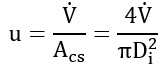
The mean fluid velocity is obtained from the volumetric flow rate:
The Reynolds number is:
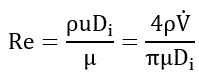
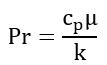
The Prandtl number is:
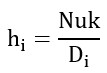
These dimensionless numbers link operating flow rate, temperature-dependent fluid properties and convective heat-transfer intensity. The internal heat-transfer coefficient is determined from:
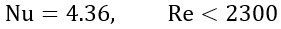
For laminar fully developed flow under approximately constant wall heat-flux conditions, the Nusselt number is:
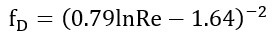
For turbulent flow, the Gnielinski correlation was adopted as the primary correlation:
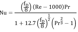
with the typical validity range:

The Gnielinski correlation was selected because it is more general than the Dittus-Boelter equation for turbulent internal flow and explicitly includes the friction factor. For reference, the Dittus-Boelter equation for turbulent heating of the fluid is:
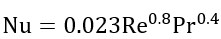
This relation was used only for consistency checking because it does not directly incorporate friction-factor effects and is less reliable close to the lower turbulent range.
The pressure drop along the absorber tube is calculated using the Darcy-Weisbach equation:
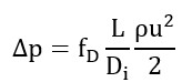
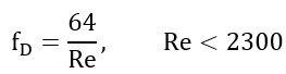
where  is the Darcy friction factor. For laminar flow:
For turbulent flow in a hydraulically smooth circular tube, the Petukhov relation is used:
In the transitional region,  , heat-transfer and friction characteristics are inherently uncertain. To avoid artificial discontinuities during optimisation, the Nusselt number and friction factor were obtained by continuous interpolation between laminar and turbulent limits.
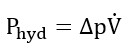
The hydraulic power required to overcome pressure drop is:
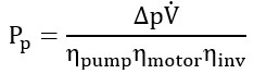
The electrical pumping power is:
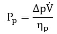
where  is the effective pump efficiency. If motor and power-conditioning losses are considered separately, the expression can be generalised as:
The physical implication is central to the optimisation. At low flow rates,  ,
,  and
and  are relatively low, resulting in a larger absorber-to-fluid temperature difference and higher receiver thermal losses. Increasing flow rate improves convection and reduces thermal resistance. However, because pressure drop increases approximately with the square of velocity in turbulent flow and pumping power is proportional to
  , excessive flow rates can reduce net useful power.
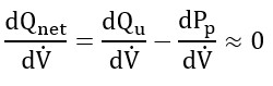
2.4. Net useful-power objective function
To evaluate the actual energetic benefit of each operating point, the gross useful heat gain was corrected by subtracting the pumping-power requirement [42]. The net useful power is defined as:
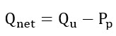
The objective of the optimisation is:
subject to:

This formulation is more suitable for practical PTC operation than maximising  or
or  alone. The optimum flow rate is the point at which the derivative of net useful power with respect to volumetric flow rate approaches zero:
A net thermal efficiency can also be defined as:
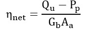
|
This parameter represents the fraction of incident solar power converted into useful heat after auxiliary circulation power is considered. In comparative fluid ranking,  and
and  were prioritised over gross thermal efficiency.
2.5. Exergy and entropy-generation model
Exergy analysis was introduced to evaluate not only the amount of useful heat delivered but also its thermodynamic quality. The useful thermal exergy associated with heat delivery at the mean fluid temperature is approximated as:
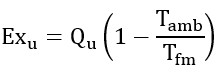
The solar exergy input is estimated using a Petela-type expression:
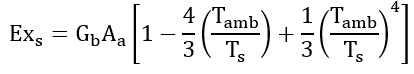
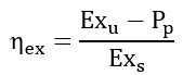
The net exergy efficiency is then defined as:
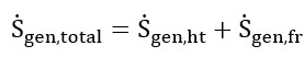
Entropy generation was separated into heat-transfer and frictional components:
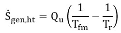
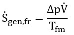
This decomposition is important because increasing flow rate has opposite effects on the two entropy-generation components. It can reduce heat-transfer entropy generation by reducing the absorber-to-fluid temperature difference, but it can increase frictional entropy generation through higher pressure drop.
2.6. Heat transfer fluids and operating range
Eight commercial heat-transfer fluids (HTFs) were examined in this study: Therminol 55, Therminol 59, Therminol 66, Therminol 68, Therminol XP, Therminol VP-1, Therminol D-12 and Syltherm 800. These fluids represent widely used synthetic and silicone-based thermal oils employed in solar-thermal and industrial heat-transfer systems. The thermophysical properties of each fluid, including density, specific heat capacity, dynamic viscosity and thermal conductivity, were considered as temperature-dependent parameters. For every operating condition, the properties were evaluated at the corresponding mean fluid temperature.
The inlet-fluid temperature was varied within the range of 273.15–523.15 K. Simulations were conducted under direct beam solar irradiance values between 700 and 1000 W m⁻², while the ambient temperature was taken in the range of 280–320 K. The volumetric flow rate was adjusted within the specified operating limits, and the optimal value was identified individually for each HTF and inlet-temperature condition. Identical collector geometry and boundary conditions were maintained for all cases to ensure a reliable and consistent comparative analysis among the investigated fluids.
2.7. Optimisation algorithm and sensitivity analysis
The optimisation was performed by maximising the net useful-energy objective. The volumetric flow rate was selected as the decision variable, while inlet temperature, irradiance, ambient temperature, fluid properties and collector geometry were treated as model inputs. The optimisation procedure consisted of the following steps: define LS-2 collector geometry and optical parameters; select the HTF and inlet temperature; evaluate temperature-dependent fluid properties; calculate velocity, Reynolds number, Prandtl number, friction factor and Nusselt number; calculate internal heat-transfer coefficient, receiver temperature, heat losses and useful heat gain; calculate pressure drop and pumping power; calculate net useful power, exergy efficiency and entropy generation; vary the volumetric flow rate; identify the flow rate that maximises net useful power; and repeat the procedure for all fluids and inlet temperatures.
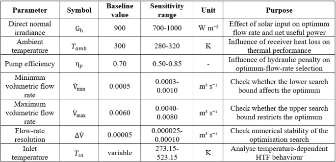
To ensure that the identified optimum flow-rate values were not strongly dependent on a single fixed operating condition, a sensitivity analysis was performed. The analysis considered the main thermal, hydraulic and numerical parameters that can influence the optimisation result, including direct normal irradiance, ambient temperature, pump efficiency, volumetric-flow-rate bounds and flow-rate resolution. The baseline values and tested sensitivity ranges are summarised in table 1.
For each sensitivity case, the optimisation procedure was repeated by varying the volumetric flow rate within the prescribed bounds and identifying the value that maximised the net useful power. This procedure was applied consistently to all investigated heat transfer fluids. The sensitivity analysis was designed to determine whether the optimum flow-rate trend and the relative ranking of the fluids remained stable under different irradiance, ambient-temperature and hydraulic-efficiency assumptions.
The inclusion of the lower and upper flow-rate bounds was necessary to verify that the optimum was not artificially constrained by the selected search interval. Similarly, the flow-rate resolution was varied to confirm the numerical stability of the optimisation procedure. Therefore, the sensitivity analysis provides an additional robustness check for the proposed thermal-hydraulic optimisation framework.
Note: The baseline case was used for the main comparison of the investigated HTFs, while the sensitivity ranges were used to evaluate the robustness of the optimum-flow-rate predictions.
3.1. Model validation and reliability
The developed thermal model was validated against the experimental SEGS LS-2 parabolic trough collector data reported by Dudley et al. [1]. Eight operating cases were selected from the reference dataset, covering different values of direct beam irradiance, ambient temperature, inlet temperature and volumetric flow rate. The experimentally measured outlet temperatures were compared with the outlet temperatures predicted by the present model. The validation results are presented in table 2.
The prediction accuracy was evaluated using the root mean square error (RMSE) and the coefficient of determination (R2), which are defined as follows:
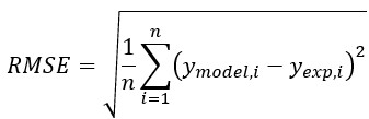
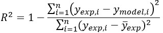
where  is the outlet temperature predicted by the present model,
  is the experimentally measured outlet temperature,
  is the mean value of the experimental outlet temperatures, and n is the number of validation points.
The comparison shows good agreement between the predicted and experimental outlet temperatures. The model produced an RMSE of 0.79 K and an R2 value of 0.99992. The low RMSE indicates that the average deviation between the model predictions and the experimental measurements is small relative to the operating-temperature range of the collector. The high R2 value further confirms that the model accurately captures the dominant thermal response of the LS-2 receiver.
It should be noted that the experimental operating conditions and measured outlet temperatures were taken from Dudley et al. [1], whereas the predicted outlet temperatures, RMSE and R2 were obtained in the present study. Therefore, the validation confirms the reliability of the receiver energy-balance formulation for outlet-temperature prediction. However, the subsequent optimum-flow-rate analysis also depends on hydraulic correlations, pump-efficiency assumptions and temperature-dependent heat-transfer-fluid property functions. For this reason, the optimisation results should be interpreted as a physically consistent comparative assessment under identical modelling assumptions rather than as a universal design rule independent of collector configuration.
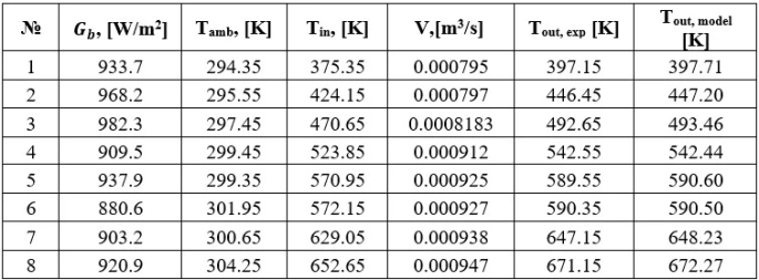
Table 2. Validation of the developed LS-2 PTC model against experimental data from Dudley et al. [1]
Note: The experimental operating conditions and outlet temperatures were taken from Dudley et al. [1], while Tout, model, RMSE and R2 were calculated in the present study.
3.2. Temperature-dependent behaviour of heat transfer fluids
The thermal-hydraulic behaviour of each HTF is strongly controlled by temperature-dependent properties. Dynamic viscosity is particularly important because it directly affects Reynolds number and pressure drop. At low temperatures, higher viscosity reduces Reynolds number and increases the pumping-power requirement. As temperature increases, viscosity generally decreases, allowing the same volumetric flow rate to produce a higher Reynolds number and more favourable convective heat transfer.
Specific heat capacity affects the amount of energy transported per unit mass flow rate. Fluids with higher heat capacity can carry more heat for the same mass flow rate, but this advantage may be offset if the fluid has high viscosity. Thermal conductivity influences the internal heat-transfer coefficient through the Nusselt relation. Density affects both mass flow rate and pressure drop. Therefore, no single thermophysical property is sufficient to determine the best fluid. The optimum ranking emerges from the combined effect of viscosity, heat capacity, density and thermal conductivity.
3.3. Optimum volumetric flow-rate map
For most of the investigated fluids, the optimum volumetric flow rate increases as the inlet temperature rises. This behaviour is mainly associated with the decrease in fluid viscosity at higher temperatures. Reduced viscosity lowers hydraulic resistance within the receiver tube and permits higher circulation rates without a corresponding increase in pumping-power demand. In addition, elevated inlet temperatures intensify thermal losses from the receiver, which makes enhanced internal convective heat transfer increasingly beneficial. As a consequence of these combined effects, the optimum operating point shifts toward higher flow rates.
Among the analysed HTFs, Therminol XP demonstrates relatively high optimum flow rates throughout the investigated temperature interval, reflecting its strong circulation and convective heat-transfer characteristics under high-temperature conditions. Therminol D-12 likewise exhibits a substantial increase in optimum flow rate with increasing temperature, indicating promising suitability for elevated-temperature applications. Therminol 66, in contrast, operates with comparatively lower optimum flow rates at lower temperatures, although its performance becomes increasingly favourable as the operating temperature rises.
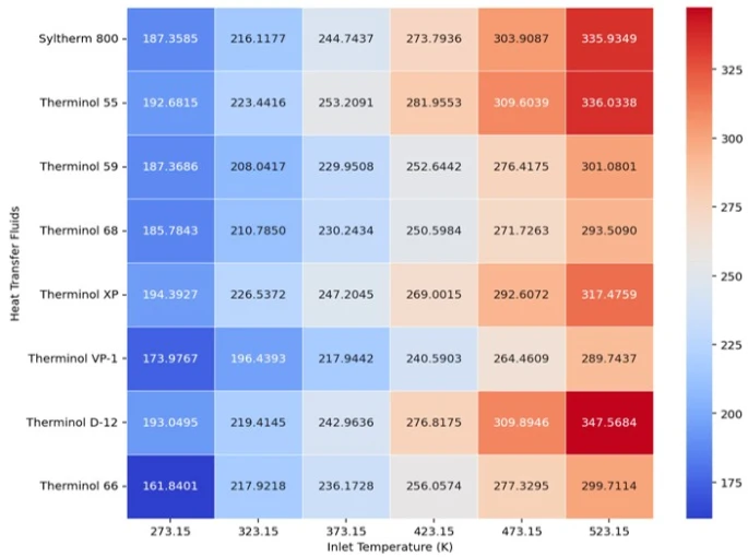
Figure 2. Heatmap of optimum volumetric flow rates for eight heat transfer fluids over the investigated inlet-temperature range
The existence of an optimum confirms that the maximum tested flow rate is not necessarily desirable. At low flow rates, heat transfer is insufficient and receiver temperature increases. At very high flow rates, the gain in useful heat becomes marginal, while pumping power continues to increase. Therefore, the optimum point reflects a balance between internal heat-transfer enhancement and hydraulic penalty.
3.4. Thermal gain versus hydraulic penalty
The net heat-power behaviour shows that most fluids experience a slight decrease in useful heat power as inlet temperature increases. This is mainly caused by higher receiver thermal losses at elevated absorber and fluid temperatures. Although higher flow rates improve internal convection, they cannot fully eliminate the increase in external heat loss.
Therminol D-12 and Therminol VP-1 maintain favourable net-energy performance across the investigated temperature range. Their advantage is associated with a combination of acceptable heat capacity, favourable viscosity behaviour and relatively low pumping-power demand. By contrast, Therminol 55 shows the largest deterioration at elevated temperatures, indicating that its thermal-hydraulic balance becomes less favourable in high-temperature operation.
The pumping-power results further demonstrate that hydraulic penalty can change the interpretation of fluid performance. A fluid may produce acceptable gross heat gain but still be unattractive if it requires excessive pumping power. Therminol VP-1 and Therminol D-12 require relatively low pumping power across the investigated conditions, which explains their strong net useful-energy performance. Therminol 66 shows high pumping-power demand at low temperatures, suggesting that cold-start or low-temperature operation may require careful flow-rate control.
Figure 3. Net useful power obtained at the optimum volumetric flow rate for each heat-transfer fluid and inlet temperature
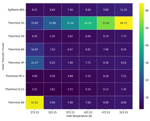
Figure 4. Pumping power required at the optimum volumetric flow rate for each heat transfer fluid and inlet temperature
3.5. Net useful-power ranking of heat transfer fluids
Looking only at the gross useful heat power, fluids with higher heat-transfer capability may initially seem more favorable. However, this picture changes once the pumping-power requirement is included in the evaluation. Under these conditions, the ranking shifts toward working fluids that provide a more reasonable balance between thermal performance and hydraulic resistance. For this reason, the net useful power (Qnet) is adopted as the main optimization criterion in this study.
Among the examined working fluids, Therminol D-12 and Therminol VP-1 consistently demonstrate the most balanced overall performance under the investigated conditions. They achieve relatively high net useful power while keeping the pumping-power demand at a moderate level. Therminol XP shows strong heat-transfer and circulation performance, particularly at higher temperatures, although its final position in the ranking is strongly influenced by the associated hydraulic losses. In contrast, Therminol 55 becomes less effective at elevated temperatures, as its performance declines more rapidly with increasing operating temperature.
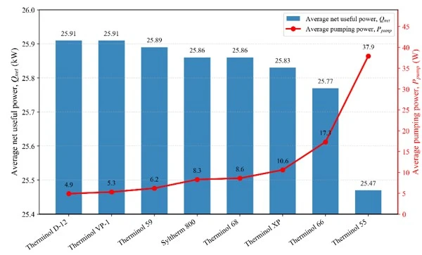
Figure 5. Average net useful power and pumping-power requirement for the investigated heat-transfer fluids under optimum flow-rate conditions. The comparison illustrates the trade-off between useful thermal output and hydraulic energy penalty
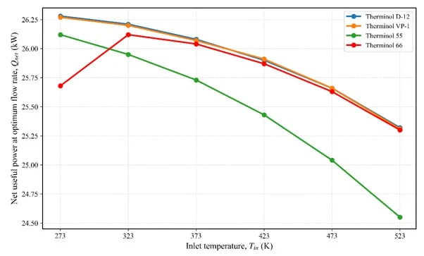
Figure 6. Temperature-dependent net heat-power trends for representative heat transfer fluids selected to illustrate favourable thermal-hydraulic behaviour, high-temperature performance deterioration and hydraulic-penalty-related effects
To further clarify the ranking behaviour, figure 6 illustrates the temperature-dependent trends of net heat power for four representative heat-transfer fluids. Therminol D-12 and Therminol VP-1 were selected as high-performing cases, as both fluids consistently combine relatively high net heat gain with comparatively low pumping-power requirements. Therminol 55 was included as a lower-performance reference due to its noticeable decline in performance at elevated inlet temperatures. Therminol 66, on the other hand, was chosen to demonstrate the effect of hydraulic losses, particularly in the low-temperature operating range. Together, these four fluids capture the main performance groups observed among the eight investigated HTFs. The full set of results for all fluids is provided in the supplementary material.
The trend confirms that the leading fluids do not only provide higher instantaneous heat gain but also maintain more stable net-energy behaviour over the investigated temperature range. In contrast, the lower-performing reference case shows a more pronounced decline as inlet temperature increases, indicating that fluid selection becomes increasingly important under high-temperature PTC operation.
3.6. Exergy and entropy-generation interpretation
Exergy analysis offers a thermodynamic perspective on the thermal–hydraulic ranking presented in the previous sections. Unlike net useful power, which reflects the delivered heat after accounting for pumping-power consumption, exergy efficiency evaluates how much of that heat can be converted into useful work relative to the surrounding environment. In this sense, a fluid with high thermal efficiency is not necessarily superior from an exergetic point of view, especially when significant hydraulic losses or irreversibilities are involved in the process.
In this context, the favourable performance of Therminol D-12 and Therminol VP-1 can be interpreted not only in energetic terms but also from a thermodynamic standpoint. Both fluids are able to sustain relatively high net heat gain while keeping pumping-power requirements limited, thereby preserving a higher portion of the useful work potential of the absorbed heat. Conversely, Therminol 55 exhibits weaker performance at elevated temperatures, as increased receiver heat losses reduce the thermodynamic quality of the delivered energy. Therminol 66 is more affected by combined thermal and hydraulic irreversibilities at lower inlet temperatures, which leads to higher entropy generation under cold operating conditions.
To further clarify this behaviour, entropy generation was evaluated at the optimum flow-rate conditions for the representative heat transfer fluids. The total entropy-generation rate was interpreted as the sum of heat-transfer irreversibility and frictional irreversibility. The heat-transfer component represents entropy generation caused by finite temperature difference between the absorber wall and the working fluid, whereas the frictional component represents irreversibility associated with pressure drop and pumping-power consumption.
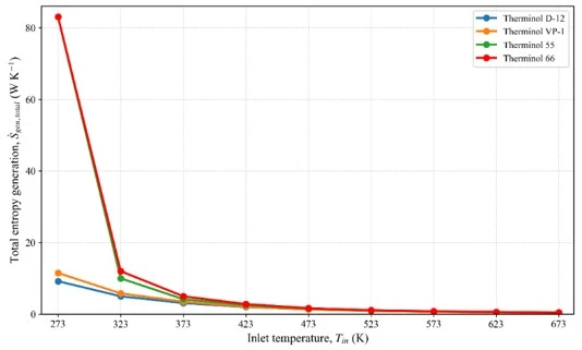
Figure 7. Total entropy generation at optimum flow-rate conditions as a function of inlet temperature for representative heat transfer fluids. The trends show lower irreversibility levels for Therminol D-12 and Therminol VP-1 and stronger low-temperature irreversibility for Therminol 55 and Therminol 66
As shown in figure 7, the total entropy generation decreases markedly with increasing inlet temperature for the representative fluids. This trend is mainly associated with the reduction in viscosity at elevated temperatures, which improves hydraulic behaviour and reduces the thermal resistance between the absorber and the working fluid. At low temperatures, Therminol 66 and Therminol 55 exhibit considerably higher entropy-generation values, indicating stronger irreversibility under cold-operation conditions. By contrast, Therminol D-12 and Therminol VP-1 maintain lower entropy-generation levels over the investigated temperature range, which supports their favourable thermal-hydraulic ranking.
The entropy-generation results confirm that the optimum flow rate should not be selected from thermal efficiency alone. At insufficient flow rates, heat-transfer irreversibility may dominate because the absorber-to-fluid temperature difference is large. At excessive flow rates, the hydraulic penalty and frictional entropy generation increase due to higher pressure drop. Therefore, the thermodynamically favourable operating condition is achieved when the reduction in heat-transfer irreversibility is balanced against the increase in hydraulic irreversibility. This interpretation supports the use of net useful power, exergy efficiency and entropy-generation behaviour as complementary criteria for volumetric flow-rate optimisation in PTC operation.
3.7. Sensitivity analysis
The sensitivity analysis was performed to evaluate the robustness of the optimum volumetric-flow-rate predictions under different operating and numerical assumptions. The main parameters considered in the analysis were direct normal irradiance, ambient temperature, pump efficiency, volumetric-flow-rate bounds and flow-rate resolution. Their baseline values and sensitivity ranges are given in table 1.
Direct normal irradiance affects the amount of solar energy available at the receiver. When irradiance increases, the thermal benefit of stronger internal convection becomes more significant because more absorbed solar energy must be transferred from the absorber wall to the working fluid. As a result, the optimum volumetric flow rate may shift towards higher values. Under lower solar irradiance conditions, the benefit gained from increasing the flow rate becomes relatively small, whereas the pumping-power requirement does not change significantly. Because of this imbalance, operating at higher flow rates becomes less attractive when the available solar input is limited.
Ambient temperature also has a noticeable impact, as it determines the temperature difference between the receiver and the surrounding air, which in turn affects heat losses from the absorber. When the ambient temperature is lower, thermal losses increase due to a larger driving temperature difference. In such situations, improving internal convection can be useful, since it helps reduce the temperature difference between the absorber wall and the working fluid and prevents excessive absorber temperatures. However, this advantage still comes at the cost of higher hydraulic losses, meaning that the optimal flow rate is only achieved when the added thermal gain is greater than the extra pumping power required.
Pump efficiency has a direct effect on the hydraulic penalty. A lower pump efficiency increases the electrical power required to overcome the same pressure drop. Therefore, when pump efficiency decreases, the optimum volumetric flow rate shifts downward because the marginal thermal benefit of stronger circulation is more rapidly offset by the additional pumping-power requirement. This result confirms that the optimum flow rate should not be treated as a fixed collector parameter, but rather as a control variable depending on fluid temperature, operating conditions and circulation-system efficiency.
The sensitivity analysis also included the lower and upper volumetric-flow-rate bounds. This was necessary to ensure that the identified optimum was not an artefact of the selected search interval. If the optimum occurs close to the lower or upper bound, the search range may artificially constrain the result. In the present analysis, the variation of the flow-rate bounds confirmed that the main optimum-flow-rate trends remained physically consistent. The flow-rate resolution was also varied to check numerical stability. The results showed that reducing the step size did not significantly change the optimum-flow-rate trends, indicating that the optimisation procedure was sufficiently stable.
Overall, the sensitivity analysis shows that inlet temperature and pump efficiency are the most influential parameters affecting the optimum volumetric flow rate. Direct normal irradiance and ambient temperature mainly influence the magnitude of the net useful power and the relative importance of internal convection. The relative advantage of Therminol D-12 and Therminol VP-1 remained stable within the tested sensitivity ranges, indicating that their favourable performance is not limited to a single operating point.
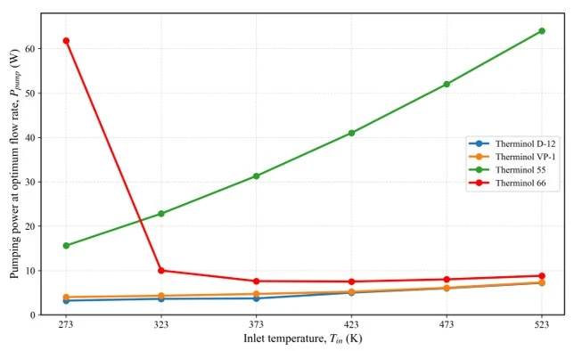
Figure 8. Pumping-power requirement at the optimum volumetric flow rate as a function of inlet temperature for representative heat transfer fluids
The pumping-power behaviour at the optimum flow-rate conditions is further illustrated in figure 8. The figure confirms that the hydraulic penalty is strongly fluid-dependent. Therminol D-12 and Therminol VP-1 maintain comparatively low pumping-power requirements over the investigated temperature range, whereas Therminol 66 shows a pronounced low-temperature pumping-power penalty. This behaviour is consistent with the strong temperature dependence of dynamic viscosity and highlights the importance of careful flow-rate control during low-temperature or cold-start operation.
3.8. Engineering implications for PTC loop design
The results provide several engineering implications for solar thermal system design and operation. First, volumetric flow rate should be treated as a temperature-dependent control variable rather than a fixed design parameter. Constant-flow operation may be suboptimal because the optimum changes with inlet temperature, solar irradiance and pump efficiency.
Second, HTF selection should be based on net useful power rather than gross thermal efficiency. Fluids should be compared using both thermal transport capability and hydraulic penalty. This is particularly important for large collector fields, where pumping-power consumption can become a non-negligible part of system operation.
Third, Therminol D-12 and Therminol VP-1 are recommended as favourable candidates under the investigated LS-2 operating conditions because they maintain high net useful power with comparatively low pumping-power demand. Therminol XP may be suitable for selected high-temperature regimes, while Therminol 55 should be used cautiously in high-temperature applications.
Fourth, low-temperature operation requires special attention because viscosity-related pumping losses may become significant. Cold-start control, gradual flow-rate ramping or fluid preheating may improve operational stability. Future industrial implementation should combine the proposed optimisation framework with economic analysis, because pumping power affects operating cost while HTF choice affects capital cost, safety, maintenance and thermal stability.
This study developed an integrated thermal-hydraulic and exergy-based framework for optimising volumetric flow rate in an LS-2 parabolic trough collector using eight commercial heat transfer fluids. The framework couples receiver energy balance, internal convection, pressure drop, pumping power, net useful power, exergy efficiency and entropy-generation indicators. The model was validated against the SEGS LS-2 experimental dataset, producing an RMSE of 0.79 K and R² = 0.99992 for outlet-temperature prediction. The main conclusions are as follows: The optimum volumetric flow rate generally increases with inlet temperature because viscosity decreases and the benefit of stronger internal convection becomes more significant at higher receiver temperatures; The maximum gross useful heat gain does not necessarily correspond to the best operating point. The optimum flow rate is obtained when the marginal thermal gain is balanced by the marginal pumping-power penalty; Therminol D-12 and Therminol VP-1 show the most favourable overall behaviour under the investigated conditions because they combine high net useful power with relatively low pumping-power demand; Therminol 55 exhibits the strongest performance deterioration at elevated temperatures and is therefore less attractive for high-temperature PTC operation; Entropy-generation analysis confirms that the optimum operating condition is governed by the balance between heat-transfer irreversibility and hydraulic irreversibility. Therefore, thermal efficiency alone is insufficient for flow-rate optimisation; The proposed framework supports temperature-dependent flow-rate control and provides a physically consistent basis for HTF selection in CSP and solar process-heat applications. The main limitation of the present study is that the optimisation is based on steady-state modelling and empirical heat-transfer and friction correlations. Although the thermal model was validated against the LS-2 dataset, further experimental validation is needed for different HTFs, transient outdoor conditions and large collector-field configurations. Future work should extend the framework to dynamic annual simulation, thermo-economic assessment, lifecycle analysis and multi-objective optimisation using advanced algorithms such as NSGA-II, particle swarm optimisation or genetic algorithms.
1 V.E. Dudley, G.J. Kolb, M. Sloan, and D. Kearney, Test results: SEGS LS-2 solar collector, SAND94-1884 (1994).
2 R. Forristall, Heat transfer analysis and modeling of a parabolic trough solar receiver implemented in Engineering Equation Solver NREL/TP-550-34169 (2003).
3 S.D. Odeh, G.L. Morrison, and M. Behnia, Solar Energy 62 (1998) 395.
4 .A. Kalogirou, Progress in Energy and Combustion Science 30(3) (2004) 231. https://doi.org/10.1016/j.pecs.2004.02.001
5 E. Fernández-García, E. Zarza, L. Valenzuela, and M. Pérez, Renewable and Sustainable Energy Reviews 14(7) (2010) 1695. https://doi.org/10.1016/j.rser.2010.03.012
6 H. Price, E. Lüpfert, D. Kearney, E. Zarza, G. Cohen, R. Gee, and R. Mahoney, Journal of Solar Energy Engineering 124(2) (2002) 109. https://doi.org/10.1115/1.1467922
7 J.A. Duffie, W.A. Beckman, Solar Engineering of Thermal Processes, 4th ed. (2013) 928p.
8 F.P. Incropera, D.P. DeWitt, T.L. Bergman, A.S. Lavine, Fundamentals of Heat and Mass Transfer, 6th ed. (2007) 999p.
9 A. Bejan, Entropy Generation Minimization 35(418-419) (1996). https://doi.org/10.1016/S0035-3159(96)80059-6
10 A. Bejan, Convection Heat Transfer, 4th ed. (2013) 685p.
11 S. Kakaç, R.K. Shah, W. Aung, Handbook of Single-Phase Convective Heat Transfer (1987) 900p.
12 V. Gnielinski, International Chemical Engineering 16 (1976) 359.
13 B.S. Petukhov, Advances in Heat Transfer 6 (1970) 503. https://doi.org/10.1016/S0065-2717(08)70153-9
14 A. Mwesigye, Bello-Ochende, J.P. Meyer, Energy 73 (2014) 661.
15 A. Mwesigye, T. Bello-Ochende, J.P. Meyer, International Journal of Thermal Sciences 99 (2016) 238. https://doi.org/10.1016/j.ijthermalsci.2015.08.015
16 A. Mwesigye, J.P. Meyer, Proceedings of the ASME International Mechanical Engineering Congress and Exposition (2017) IMECE2017-70122.
17 A. Mwesigye, İ.H. Yılmaz, Journal of Molecular Liquids 319 (2020) 114151.
18 Eastman Chemical Company, Therminol heat transfer fluids: product and technical information (2024).
19 Eastman Chemical Company, Therminol 66 heat transfer fluid technical bulletin (2024).
20 Eastman Chemical Company, Therminol VP-1 heat transfer fluid technical bulletin (2024).
21 Dow, Syltherm 800 silicone heat transfer fluid technical data sheet (2024).
22 F. Burkholder, C. Kutscher, Heat loss testing of Schott’s 2008 PTR70 parabolic trough receiver (2008).
23 K.S. Reddy, K. Ravi Kumar, C.S. Ajay, Renewable Energy 77 (2015) 308. https://doi.org/10.1016/j.renene.2014.12.016
24 E. Bellos, C. Tzivanidis, Journal of Thermal Analysis and Calorimetry 135(2) (2018) 763. https://doi.org/10.1007/s10973-018-7183-1
25 E. Bellos, C. Tzivanidis, K.A. Antonopoulos, Applied Thermal Engineering 114 (2017) 374. https://doi.org/10.1016/j.applthermaleng.2016.11.201
26 E. Bellos, C. Tzivanidis, D. Tsimpoukis, Applied Energy 205 (2017) 540. https://doi.org/10.1016/j.apenergy.2017.07.141
27 A. Kasaeian, R. Daneshazarian, O. Mahian, L. Kolsi, A.J. Chamkha, International Journal of Heat and Mass Transfer 107 (2017) 778. https://doi.org/10.1016/j.ijheatmasstransfer.2016.11.074
28 Z. Said, R. Saidur, M.A. Sabiha, A. Hepbasli, N.A. Rahim, Journal of Cleaner Production 112 (2016) 3915. https://doi.org/10.1016/j.jclepro.2015.07.115
29 S.K. Verma, A.K. Tiwari, D.S. Chauhan, Renewable and Sustainable Energy Reviews 78 (2017) 1106.
30 S.K. Singh, A.K. Tiwari, H.K. Paliwal, Energy Sources Part A 45(4) (2023) 10682.
31 S.K. Singh, A.K. Tiwari, H.K. Paliwal, Energy Sources Part A 45(4) (2023) 10682. https://doi.org/10.1080/15567036.2023.2248936
32 S.K. Basha, A.K. Behura, Energy Sources Part A 46 (2024) 16675. https://doi.org/10.1080/15567036.2024.2430416
33 D.Y. Jalilov, T.I. Juraev, A.Y. Ibodullaev, S.L. Lutpullaev, A.S. Halimov, Applied Solar Energy 60 (2024) 27. https://doi.org/10.3103/s0003701x24600127
34 D.Y. Jalilov, T.I. Juraev, J.S. Akhatov, Applied Solar Energy 60 (2024) 281. https://doi.org/10.3103/S0003701X23602077
35 S.A. Kalogirou, Progress in Energy and Combustion Science 56 (2016) 106. https://doi.org/10.1016/j.pecs.2016.05.002
36 M.C. Ndukwu, L. Bennamoun, M. Simo-Tagne, Energies 14(3) (2021) 724. https://doi.org/10.3390/en14030724
37 R.M. Mostafizur, M.G. Rasul, M.N. Nabi, Energies 14(4) (2021) 4305. https://doi.org/10.3390/en14144305
38 A. Mwesigye, T. Bello-Ochende, J.P. Meyer, Energy 53 (2013) 114. https://doi.org/10.1016/j.energy.2013.03.006
39 S.M. Tabarhoseini, M. Sheikholeslami, D.D. Ganji, Scientific Reports 12 (2022) 2232.
40 Bejan, Entropy Generation Minimization: The Method of Thermodynamic Optimization of Finite-Size Systems and Finite-Time Processes, Boca Raton, CRC Press (1996) 400p.
41 M. Muñoz, M. Roa, R. Correa, DYNA 87(212) (2020) 199. https://doi.org/10.15446/dyna.v87n212.80111
42 D.Y. Jalilov, T.I. Juraev, A.S. Halimov, J.S. Akhatov, Next Research 2(3) (2025) 100470. https://doi.org/10.1016/j.nexres.2025.100470
D. Jalilov, T. Juraev, A. Halimov, Zh. Tian, J. Akhatov, Integrated thermal-hydraulic and exergy-based optimisation of volumetric flow rate in parabolic trough collectors using commercial heat transfer fluids, UNECJ. Eng. Appl. Sci. 6(1) (2026) 39-58. https://doi.org/10.61640/ujeas.2026.0504
Anyone you share the following link with will be able to read this content:
This article is licensed under the Creative Commons Attribution ( CC BY 4.0 ) License, which permits unrestricted use, distribution, and reproduction in any medium, provided the original author and source are credited.
V.E. Dudley, G.J. Kolb, M. Sloan, and D. Kearney, Test results: SEGS LS-2 solar collector, SAND94-1884 (1994).
R. Forristall, Heat transfer analysis and modeling of a parabolic trough solar receiver implemented in Engineering Equation Solver NREL/TP-550-34169 (2003).
S.D. Odeh, G.L. Morrison, and M. Behnia, Solar Energy 62 (1998) 395.
.A. Kalogirou, Progress in Energy and Combustion Science 30(3) (2004) 231. https://doi.org/10.1016/j.pecs.2004.02.001
E. Fernández-García, E. Zarza, L. Valenzuela, and M. Pérez, Renewable and Sustainable Energy Reviews 14(7) (2010) 1695. https://doi.org/10.1016/j.rser.2010.03.012
H. Price, E. Lüpfert, D. Kearney, E. Zarza, G. Cohen, R. Gee, and R. Mahoney, Journal of Solar Energy Engineering 124(2) (2002) 109. https://doi.org/10.1115/1.1467922
J.A. Duffie, W.A. Beckman, Solar Engineering of Thermal Processes, 4th ed. (2013) 928p.
F.P. Incropera, D.P. DeWitt, T.L. Bergman, A.S. Lavine, Fundamentals of Heat and Mass Transfer, 6th ed. (2007) 999p.
A. Bejan, Entropy Generation Minimization 35(418-419) (1996). https://doi.org/10.1016/S0035-3159(96)80059-6
A. Bejan, Convection Heat Transfer, 4th ed. (2013) 685p.
S. Kakaç, R.K. Shah, W. Aung, Handbook of Single-Phase Convective Heat Transfer (1987) 900p.
V. Gnielinski, International Chemical Engineering 16 (1976) 359.
B.S. Petukhov, Advances in Heat Transfer 6 (1970) 503. https://doi.org/10.1016/S0065-2717(08)70153-9
A. Mwesigye, Bello-Ochende, J.P. Meyer, Energy 73 (2014) 661.
A. Mwesigye, T. Bello-Ochende, J.P. Meyer, International Journal of Thermal Sciences 99 (2016) 238. https://doi.org/10.1016/j.ijthermalsci.2015.08.015
A. Mwesigye, J.P. Meyer, Proceedings of the ASME International Mechanical Engineering Congress and Exposition (2017) IMECE2017-70122.
A. Mwesigye, İ.H. Yılmaz, Journal of Molecular Liquids 319 (2020) 114151.
Eastman Chemical Company, Therminol heat transfer fluids: product and technical information (2024).
Eastman Chemical Company, Therminol 66 heat transfer fluid technical bulletin (2024).
Eastman Chemical Company, Therminol VP-1 heat transfer fluid technical bulletin (2024).
Dow, Syltherm 800 silicone heat transfer fluid technical data sheet (2024).
F. Burkholder, C. Kutscher, Heat loss testing of Schott’s 2008 PTR70 parabolic trough receiver (2008).
K.S. Reddy, K. Ravi Kumar, C.S. Ajay, Renewable Energy 77 (2015) 308. https://doi.org/10.1016/j.renene.2014.12.016
E. Bellos, C. Tzivanidis, Journal of Thermal Analysis and Calorimetry 135(2) (2018) 763. https://doi.org/10.1007/s10973-018-7183-1
E. Bellos, C. Tzivanidis, K.A. Antonopoulos, Applied Thermal Engineering 114 (2017) 374. https://doi.org/10.1016/j.applthermaleng.2016.11.201
E. Bellos, C. Tzivanidis, D. Tsimpoukis, Applied Energy 205 (2017) 540. https://doi.org/10.1016/j.apenergy.2017.07.141
A. Kasaeian, R. Daneshazarian, O. Mahian, L. Kolsi, A.J. Chamkha, International Journal of Heat and Mass Transfer 107 (2017) 778. https://doi.org/10.1016/j.ijheatmasstransfer.2016.11.074
Z. Said, R. Saidur, M.A. Sabiha, A. Hepbasli, N.A. Rahim, Journal of Cleaner Production 112 (2016) 3915. https://doi.org/10.1016/j.jclepro.2015.07.115
S.K. Verma, A.K. Tiwari, D.S. Chauhan, Renewable and Sustainable Energy Reviews 78 (2017) 1106.
S.K. Singh, A.K. Tiwari, H.K. Paliwal, Energy Sources Part A 45(4) (2023) 10682.
S.K. Singh, A.K. Tiwari, H.K. Paliwal, Energy Sources Part A 45(4) (2023) 10682. https://doi.org/10.1080/15567036.2023.2248936
S.K. Basha, A.K. Behura, Energy Sources Part A 46 (2024) 16675. https://doi.org/10.1080/15567036.2024.2430416
D.Y. Jalilov, T.I. Juraev, A.Y. Ibodullaev, S.L. Lutpullaev, A.S. Halimov, Applied Solar Energy 60 (2024) 27. https://doi.org/10.3103/s0003701x24600127
D.Y. Jalilov, T.I. Juraev, J.S. Akhatov, Applied Solar Energy 60 (2024) 281. https://doi.org/10.3103/S0003701X23602077
S.A. Kalogirou, Progress in Energy and Combustion Science 56 (2016) 106. https://doi.org/10.1016/j.pecs.2016.05.002
M.C. Ndukwu, L. Bennamoun, M. Simo-Tagne, Energies 14(3) (2021) 724. https://doi.org/10.3390/en14030724
R.M. Mostafizur, M.G. Rasul, M.N. Nabi, Energies 14(4) (2021) 4305. https://doi.org/10.3390/en14144305
A. Mwesigye, T. Bello-Ochende, J.P. Meyer, Energy 53 (2013) 114. https://doi.org/10.1016/j.energy.2013.03.006
S.M. Tabarhoseini, M. Sheikholeslami, D.D. Ganji, Scientific Reports 12 (2022) 2232.
Bejan, Entropy Generation Minimization: The Method of Thermodynamic Optimization of Finite-Size Systems and Finite-Time Processes, Boca Raton, CRC Press (1996) 400p.
M. Muñoz, M. Roa, R. Correa, DYNA 87(212) (2020) 199. https://doi.org/10.15446/dyna.v87n212.80111
D.Y. Jalilov, T.I. Juraev, A.S. Halimov, J.S. Akhatov, Next Research 2(3) (2025) 100470. https://doi.org/10.1016/j.nexres.2025.100470