UNEC Journal of Engineering and Applied Sciences Volume 5, No 2, pages 5-16 (2025) Cite this article, ![]() 3131 https://doi.org/10.61640/ujeas.2025.1201
3131 https://doi.org/10.61640/ujeas.2025.1201
Aviation technology is one of the most revolutionary and rapidly advancing fields in modern science and engineering. It has transformed the way we travel, connect, and explore the world. Aeronautical engineering, a vital part of aviation, plays a foundational role in advancing space science and developing technologies for aircraft and spacecraft. This field combines principles of design, material science, and structural engineering to ensure that aircraft are safe, efficient, and reliable.
In recent years, developing countries have been making significant strides in expanding their aviation industries. This progress is driven by the growing need for advanced materials and innovative designs that improve the performance and efficiency of aircraft. Among the most critical components of an aircraft are its wings, which are responsible for generating lift. The wing structure is a complex system that includes the skin, ribs, and spars, each of which has a specific role in ensuring the wing's functionality and strength. The spar is the primary load-carrying member, supporting the flight loads during operation and the weight of the wings while on the ground. Ribs, attached to the spar, provide additional support and help maintain the aerodynamic shape of the wing, while the stressed skin ensures the wing can withstand the forces it encounters during flight.
Wings are the most important lift-producing parts of an aircraft. Their design varies based on factors such as the size, weight, speed, rate of climb, and intended use of the aircraft. For example, combat aircraft require wings designed to handle extreme stresses during high-speed manoeuvres, while transport aircraft need wings that can support heavy loads during long-haul flights. Approximately 80% of the lift load in a transport aircraft is carried by the wing structure, making it crucial to design wings that are both strong and lightweight.
Experimental testing of wing structures, while important, is often expensive and time-consuming. As a result, computational methods such as finite element analysis (FEA) are increasingly used to analyze wing designs. These methods allow engineers to simulate the stresses, loads, and deformations that a wing will experience during operation, providing valuable insights without the need for physical prototypes.
The materials used in constructing wing structures are equally important. Aluminum alloys are widely used in modern aircraft because of their high strength-to-weight ratio, corrosion resistance, and ease of fabrication. Aluminum's lightweight nature makes it an ideal material for creating aircraft structures that are both strong and efficient. However, in certain applications where aluminum may be too weak or heavy materials like stainless steel are unsuitable, titanium has emerged as a superior alternative. Titanium is lightweight, strong, corrosion-resistant, and unaffected by long-term exposure to seawater and marine environments. Recent advancements in material science have made titanium an excellent choice for high-performance aircraft, where strength and durability are critical.
The design and construction of wing structures involve balancing multiple factors, including aerodynamics, material properties, and operational requirements. Wings must maintain their shape under the extreme stresses of flight while ensuring the aircraft can perform efficiently and safely. Modern aircraft, particularly naval aircraft, often feature full cantilever wing structures that are strong enough to eliminate the need for external bracing such as wires or struts. This type of construction improves the aerodynamic performance of the aircraft while maintaining structural integrity.
According to Kumar's (2015) [1] research in "Investigation of Aerofoil Design," an asymmetric aerofoil has a higher lift coefficient than a symmetric one at the same angle of attack and with the comparable chord length and maximum camber. In a study called "Modeling and Investigation on Wing of A380 Flight," the Airbus A380 wing was subjected to temperature and structural analyses. The wing's safety was assessed through the use of stress, strain, and thermal flux calculations. We used CATIA for the modeling and ANSYS, a FEA tool, for the analysis. Both the stress and strain values that were simulated were found to be within acceptable ranges. Although the computed stress was just 400 Pa, the wing could endure a maximum of 700 Pa.
Transport aircraft wing analysis was performed by Abbas et al. (2021) [2] using Catia V5 as modelling tool and Ansys 2016 as solver. From this study it is observed that stresses caused by the aerodynamic loads on the wing are within the design structural limits where the failure by yield or buckling has not been occurred. A modal analysis of an airplane wing was presented by Khadse and Zaweri [3] (2015). We used ProE 5.0 to build the wing CAD model, and ANSYS Workbench 14.0 for the modal analysis. In order to conduct the analysis, the root chord of the wing was fixed while the tip chord remained free. Cantilever beam modal analysis was also performed to validate the simulation. The findings validated the FE model's accuracy by demonstrating tight agreement between theoretical and numerical methods. The impact of angle of view on airfoil efficiency was studied by Gultop [4] (1995). The objective of the study was to analyze the conditions of ripples while conducting wind tunnel testing. According to the results, aero-elastic instabilities happened at a Mach number of 0.55, which is greater than the 0.3 limit set by the wind tunnel. Das and Jones [5] (2002) investigated the optimal shape of a fuel flow vent hole in the F-111 wing pivot fitting using damage-tolerance-based optimization in their article "Damage Tolerance-Based Design Optimization of a Fuel Flow Vent Hole in an Aircraft Structure" (published in the Journal of Structural Multidisciplinary Optimization). The aerospace, maritime, and mining sectors are frequent users of such cuts in engineering structures for the purpose of weight reduction or equipment passage. Three important design criteria—stress, residual strength, and fatigue life—were employed to optimize the vent hole form in the study. The study "Static Analysis of Transversely Loaded Isotropic and Orthotropic Plates with Central Cutout" (1998) by Kalita and Halder [6] was published in the Journal of the Institution of Engineers. The authors determined that, under different boundary conditions, the cutout peripheral experiences the highest shear stress. Deflection was found to be maximal close to the cutting and decreasing as one approached the restrictions. Orthotropic plates have larger stress concentration factors (SCF) than isotropic plates, the study found, since the two types of plates have different elastic constants. By applying suitable loads, the induced stresses were purposefully maintained within the elastic range. A finite element analysis was performed to assess the structural stability of a high-wing cable-supported ultralight aircraft by Baughn and Packman [7] (1986). While flying level and landing with two wheels, a macro-model with a symmetrical half-structure was examined. Both the supported and unsupported wings had their flexural and bending stiffness measured in the study. After removing several cable components and wing compression struts, we redistributed the loads, assessed the damage tolerance, and looked at other flight configurations. Converting high-wing cable-supported aircraft to strut-supported designs was suggested.
Aircraft owners frequently make aerodynamic improvements to their high-wing cable-supported ultralights. The study examined the modification's effect on drag reduction and compared the structural performance of aircraft supported by cables with those supported by struts. The findings demonstrated that shifting to a strut-supported design improved overall performance while decreasing drag. The structural behavior of an airplane wing was the primary focus of the study by Sruthi et al. (2017) [8], which compared the use of conventional aluminum alloys with composites made of aluminum and silicon carbide. The analysis was carried out utilizing ANSYS software's Finite Element Modeling (FEM) and linear static analysis tools to assess structural performance, deformation, and stress.
The primary objective was to ascertain if Al + SiC composites could enhance wing performance by providing improved strength-to-weight ratios. Comparing the two materials, we found very little variation in deformation, equivalent stress, primary stress, stress intensity, and shear stress. The combination of aluminum and silicon carbide did have a few benefits over aluminum alloys, though. It was lighter, stronger, and more resistant to fatigue. The study found that aircraft wings may be strengthened, made more efficient, and kept structurally sound by replacing conventional aluminum alloys with composites made of aluminum and silicon carbide. Future aircraft wing designs may want to consider Al + SiC after this analysis proved the wing structure wouldn't collapse under the expected loading circumstances.
Finding the optimum spot between light weight and strength in aircraft wing material selection is the primary goal of the research. The wing structure can be more precisely analyzed with the use of ANSYS and Finite Element Analysis (FEA) software, which reduces the necessity for expensive and time-consuming physical prototyping. When comparing the deformation values provided by NACA 25206 to the theoretical values for several conventional materials, the results of the CAD model validation demonstrated that NACA 25206 provided the best results. Aluminum alloys were chosen for more investigation after structural analysis showed that structural steel, although offering the least deformation, is inappropriate due to its high density. From these data available from various researchers it can be concluded that the model was accurate and that aluminum alloys are the best material to employ based on the FEA results. This opens the door to investigating composites as a potential next step in improving wing performance.
Similar, studies have been performed by Basri et al. [9] to study the performance of composite ply orientation for the aeronautical applications especially for the NACA4415 wing of UAV. Multilayered composite laminates structural analysis on wings was made by Basri et al. [10], using FE-ACP simulator the aerodynamic loading was evaluated interms of deformation. Using ANSYS Fluid tool [11,12] few researchers have made fluid dynamic study which will affect the wind structure/various loads acting on wings. These loads will affect the wing design. Naeem [13] has made an attempt to study the Structural and Stress Analysis of NACA0012 Wing Using SolidWorks and they found that, stress resulting from the numerical analysis under the influence of the aerodynamic force is less than the yield strength of the structural material.
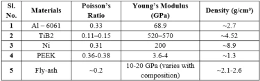
Materials
Materials were categorised as a hybrid composite because it involves multiple types of reinforcements (both ceramic and polymeric) embedded in a metal matrix. Following table 1 shows the material selected for the analysis of aircraft wing fabricated with various materials.
Methods
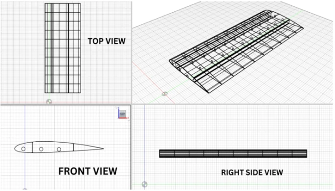
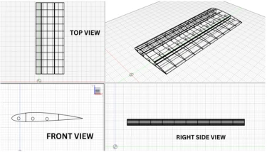
Acquiring adequate data regarding the wing design parameters is critical to launch in the present study. In many of the steps involved in finding the solution for the wing analysis problems, first step is to design the wing according to our specifications. Even if we don't have access to all the necessary design details, we can still use information from straight wings with rectangular plans that have been made by other companies. With this information, we can determine the wing's outward characteristics. In the present study ANSYS Software is being used to design the wing once the dimensions have been specified. After that, the same program is used to do structural analysis. We are able to compute and analyze the structural loads on the wings under different flying situations with the help of ANSYS.
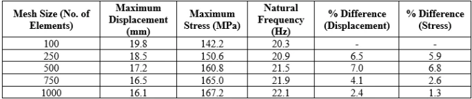
Convergence Study
Table 2 depicts the results of convergence study carried on a model which was modelled to check the adoptability of the tool for the study. From this, it is observed that, displacement and stress measurements exhibit considerable variation between 100 and 500 elements, indicating that 100 to 250 elements are insufficient for obtaining meaningful findings. Results commence stabilization from the 750th element forward. Approximately 1,000 elements may be permissible for preliminary conceptual investigations. Assumed wing geometry: a simplified cantilever wing section featuring an aerodynamic profile.
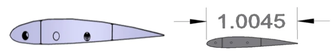
Standards used for the Model preparation in AutoCAD
Dimensions: 190.5mm x 254mm x 6mm
Wing Span: 5300mm
Total Thickness: 65mm at 14%
Rib Thickness: root: 47mm
Taper ratio: 1
chord length 1150 mm at 29.5%
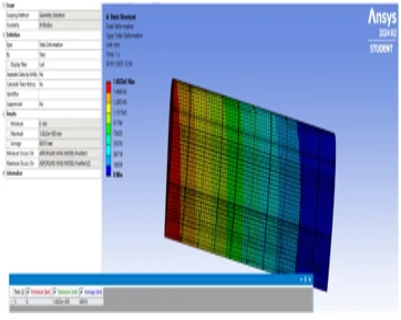
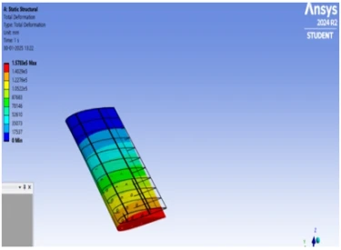
The Finite Element Method (FEM) is one the old and approximate solution technique and also known as numerical method of solving plenty of simple and complex mechanical/civil and other engineering problems (especially structure and stress related analysis). Many researchers/academicians [14-18] have employed, various software’s and programmed software’s to describe the behaviour of the various problems under various conditions (such as Boundary conditions, load conditions (static/dynamic), vibration etc.) that too to analyse (static stress study and numerical design of the wing) the aircraft wing structure [19, 20]. With two different conditions the wings were analyzed in the present study. Selected conditions are categorized into two types namely material and applied pressure. Under material there is only one difference between case I and II that is in case – I Al6061 + Ni + PEEK and TiB2 were used but in Case – II instead of PEEK, fly-ash is being used. And applied pressure was selected as 200 MPa for case – I and 350 MPa for case – II. Following figures 2 through 5 depicts the principal stress, nodal solution, Nodal solution for directional deformation, Nodal solution for equivalent elastic strain and other detailed results for the above-mentioned conditions.
Case-I:
(i) Material: AL6061 + Ni + PEEK +TiB2 and Pressure Applied: 200MPa

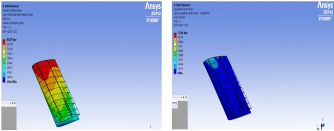
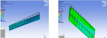
Figure 2. FEM Results for AL6061 + Ni + PEEK +TiB2 composites at 200 MPa pressure a) maximum principal stress, b) nodal solution for shear stress

c) nodal solution for directional deformation, d) nodal solution for equivalent elastic strain
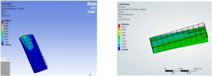
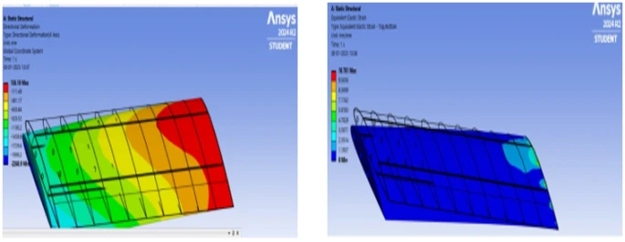
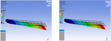
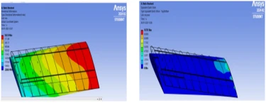
Figure 3. FEM Results for AL6061 + Ni + PEEK +TiB2 composites at 350MPa pressure a) maximum principal stress, b) nodal solution for shear stress
a) b)
c) nodal solution for directional deformation, d) nodal solution for equivalent elastic strain
c) d)
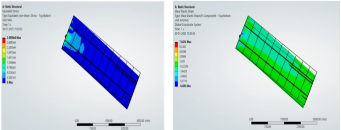
e) nodal solution for equivalent stress f) nodal solution for shear elastic strain
e) f)
Case-II
(i) Material: AL6061 + Ni + FLYASH +TiB2, and Pressure Applied: 200MPa
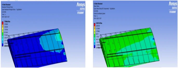
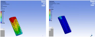
Figure 4. FEM Results for AL6061 + Ni + Fly-ash +TiB2 composites at 200 MPa pressure a) maximum principal stress, b) nodal solution for shear stress
a) b)
c) nodal solution for directional deformation, d) nodal solution for equivalent elastic strain
c) d)
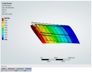
(ii) Material: AL6061 + Ni + Fly-Ash +TiB2, Pressure Applied: 350MPa
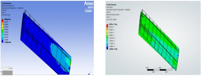
Figure 5. FEM Results for AL6061 + Ni + Fly-ash +TiB2 composites at 350 MPa pressure a) maximum principal stress, b) nodal solution for shear stress
a) b)
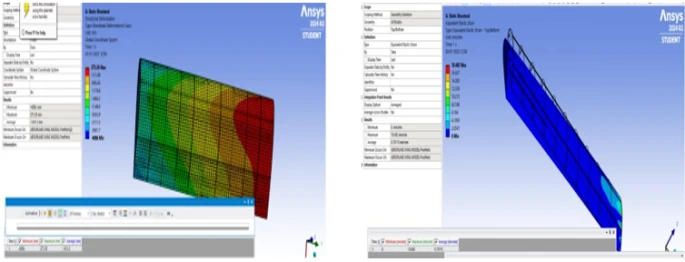
c) nodal solution for directional deformation, d) nodal solution for equivalent elastic strain
c) d)
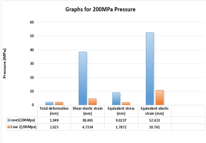
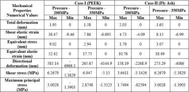
Table 3 summarizes the numerical results obtained for the aeroplane wing panel under two different conditions. Compared to case I results case II deformation was found to be increased, elastic strain was found to be reduced, stress was found to be reduced, elastic strain was found to be reduced, similarly directional deformation, shear stress and maximum principal stresses were found to be reduced.
From table 3 and figure 6 following observations were made to understand the mechanism of reinforcement replacements with varying pressure.
After looking at the results, PEEK is clearly the better choice for an airplane wing compared to Fly Ash. The main reason is that PEEK is stronger, more flexible, and resists deformation better, which is crucial for something as important as an aircraft wing.
During a flight, wings go through a lot of stress from air pressure, wind forces, and changing conditions. PEEK holds its shape better and can handle these stresses without bending too much or breaking down over time. It also has better strength and elasticity, meaning it can take more force without cracking or weakening. Fly Ash, on the other hand, shows more deformation and lower strength, which could make it less reliable, especially in high-performance aircraft.
While Fly Ash might be cheaper or lighter in some cases, when it comes to safety, durability, and long-term performance, PEEK is the smarter choice for airplane wings. It provides better strength, stability, and reliability, making it the best material for the job.
1 A. Kumar, “Investigation of Airfoil Design”, B. Tech Report submitted to National Institute of Technology Rourkela, Rourkela 769008, Odisha, India.
2 Y. Abbas, T. Elsonni, A.A. Abdulmajid, A. Khalafallh, M. Alnazir, Incas bulletin 13(1) (2021) 3. https://doi.org/10.13111/2066-8201.2021.13.1.1
3 N.A. Khadse and S.R. Zaweri, International Journal of Engineering Research & Technology 4 (07) (2015).
4 T. Gultop, American Journal of Applied Sciences 2(2) (1995) 545.
5 R. Das, R. Jones, Journal of Structural Multidisciplinary Optimization 38 (2002) 245.
6 K. Kalita, S. Halder, Journal of Institution of Engineers (India series) C 95(4) (2014) 347. https://doi.org/10.1007/s40032-014-0138-9
7 T.V. Baughn, D.B. Johnson, SAE Transactions95(5) (1986) 366. https://doi.org/10.4271/861388
8 K. Sruthi, T.L. Kishore, M.K. Rao, International Journal of Engineering Development and Research 5(4) (2017) 949.
9 E.I. Basri, M.T.H. Sultan, M. Faizal, A.A. Basri, M.S. Abdul Majid, J.S. Mandeep, Kamarul A. Ahmad, M.F. Abas, Journal of Materials Research and Technology 8(5) (2019) 3822. https://doi.org/10.1016/j.jmrt.2019.06.044
10 E.I. Basri, M.T.H. Sultan and K.A. Ahmad, F. Mustapha, A.A. Basri, Materials 14 (2021) 3705. https://doi.org/10.3390/ma14133705
11 E.I. Basri, A.A. Basri, S. Balakrishnan, M.T.H.H. Sultan & K.A. Ahmad, Mechanics Based Design of Structures and Machines 52(2) (2024) 922. https://doi.org/10.1080/15397734.2022.2126983
12 G.Vigneshwaran, M.Vijayaraghavan, K.Sivamanikandan, K.Keerthana, K.Balaji, International Journal of Engineering Research and Development 13(4) (2017) 27.
13 S.M. Naeem, Mathematical Modelling of Engineering Problems 11(8) (2024) 2181. https://doi.org/10.18280/mmep.110820
14 A. Laiche, A. Boulahia, International Journal of Advanced Research in Engineering and Technology 13(5) (2022) 32. https://doi.org/10.17605/OSF.IO/N42SB
15 S.P. Peruru, S.B. Abbisetti, International Research Journal of Engineering and Technology 4(06) (2017) 2133.
16 M.F. Rabbey, A.M. Rumi, F.H. Nuri, H.M. Monerujjaman, M.M. Hassan, Advanced Materials Research 906 (2014) 318. https://doi.org/10.4028/www.scientific.net/AMR.906.318
17 S.S. Krishna, N. Priyatham, International Journal of Mechanical and Production Engineering Research and Development 11(4) (2021) 1837.
18 S.K. Das, S. Roy, IOP Conference Series: Materials Science and Engineering 402(1) (2018) 012077. https://doi.org/10.1088/1757-899X/402/1/012077
19 U. Tariq, F. Mazhar, In 2021 International Bhurban Conference on Applied Sciences and Technologies (IBCAST), Islamabad, Pakistan (2021) 221. https://doi.org/10.1109/IBCAST51254.2021.9393241
20 A. Schütte, D. Hummel, Numerical design studies on the roll stability of a multi-delta-wing configuration. Journal of Aircraft 60(3) (2022). https://doi.org/10.2514/1.C037128
I. Shikkerimath, V. Ventakaramana, R. Jadar, Hemaraju, A.R. Banagar, B.T. Ramesh, Modeling and structural analysis of aircraft wing using composite materials in ANSYS workbench, UNEC J. Eng. Appl. Sci. 5(2) (2025) 5-16. https://doi.org/10.61640/ujeas.2025.1201
Anyone you share the following link with will be able to read this content:
This article is licensed under the Creative Commons Attribution ( CC BY 4.0 ) License, which permits unrestricted use, distribution, and reproduction in any medium, provided the original author and source are credited.


A. Kumar, “Investigation of Airfoil Design”, B. Tech Report submitted to National Institute of Technology Rourkela, Rourkela 769008, Odisha, India.
Y. Abbas, T. Elsonni, A.A. Abdulmajid, A. Khalafallh, M. Alnazir, Incas bulletin 13(1) (2021) 3. https://doi.org/10.13111/2066-8201.2021.13.1.1
N.A. Khadse and S.R. Zaweri, International Journal of Engineering Research & Technology 4 (07) (2015).
T. Gultop, American Journal of Applied Sciences 2(2) (1995) 545.
R. Das, R. Jones, Journal of Structural Multidisciplinary Optimization 38 (2002) 245.
K. Kalita, S. Halder, Journal of Institution of Engineers (India series) C 95(4) (2014) 347. https://doi.org/10.1007/s40032-014-0138-9
T.V. Baughn, D.B. Johnson, SAE Transactions95(5) (1986) 366. https://doi.org/10.4271/861388
K. Sruthi, T.L. Kishore, M.K. Rao, International Journal of Engineering Development and Research 5(4) (2017) 949.
E.I. Basri, M.T.H. Sultan, M. Faizal, A.A. Basri, M.S. Abdul Majid, J.S. Mandeep, Kamarul A. Ahmad, M.F. Abas, Journal of Materials Research and Technology 8(5) (2019) 3822. https://doi.org/10.1016/j.jmrt.2019.06.044
E.I. Basri, M.T.H. Sultan and K.A. Ahmad, F. Mustapha, A.A. Basri, Materials 14 (2021) 3705. https://doi.org/10.3390/ma14133705
E.I. Basri, A.A. Basri, S. Balakrishnan, M.T.H.H. Sultan & K.A. Ahmad, Mechanics Based Design of Structures and Machines 52(2) (2024) 922. https://doi.org/10.1080/15397734.2022.2126983
G.Vigneshwaran, M.Vijayaraghavan, K.Sivamanikandan, K.Keerthana, K.Balaji, International Journal of Engineering Research and Development 13(4) (2017) 27.
S.M. Naeem, Mathematical Modelling of Engineering Problems 11(8) (2024) 2181. https://doi.org/10.18280/mmep.110820
A. Laiche, A. Boulahia, International Journal of Advanced Research in Engineering and Technology 13(5) (2022) 32. https://doi.org/10.17605/OSF.IO/N42SB
S.P. Peruru, S.B. Abbisetti, International Research Journal of Engineering and Technology 4(06) (2017) 2133.
M.F. Rabbey, A.M. Rumi, F.H. Nuri, H.M. Monerujjaman, M.M. Hassan, Advanced Materials Research 906 (2014) 318. https://doi.org/10.4028/www.scientific.net/AMR.906.318
S.S. Krishna, N. Priyatham, International Journal of Mechanical and Production Engineering Research and Development 11(4) (2021) 1837.
S.K. Das, S. Roy, IOP Conference Series: Materials Science and Engineering 402(1) (2018) 012077. https://doi.org/10.1088/1757-899X/402/1/012077
U. Tariq, F. Mazhar, In 2021 International Bhurban Conference on Applied Sciences and Technologies (IBCAST), Islamabad, Pakistan (2021) 221. https://doi.org/10.1109/IBCAST51254.2021.9393241
A. Schütte, D. Hummel, Numerical design studies on the roll stability of a multi-delta-wing configuration. Journal of Aircraft 60(3) (2022). https://doi.org/10.2514/1.C037128