UNEC Journal of Engineering and Applied Sciences Volume 4, No 1, pages 43-54 (2024) Cite this article, ![]() 3249 https://doi.org/10.61640/ujeas.2024.0504
3249 https://doi.org/10.61640/ujeas.2024.0504
Protection systems have a long history, and providing protection against lightning has always been an important issue. In the past, the effectiveness of the lightning protection has been demonstrated by theoretical calculations or experimentally [1- 3]. In [1], using the transmission line protection practice, an analytical study was introduced for the protective effects of the basic lightning elements (vertical rods and horizontal wires) and a simplified shielding determination procedure was presented. In [2], the lightning protection system was modelled in laboratory to obtain the surge current distribution in conductive elements of building constructions and a mathematical method of the theoretical analysis is introduced. In [3], a lightning progression model is used for the lightning protection system. The performance of the system was examined both in a laboratory-scale experimental sample system and in the simulation of a real-sized protection system. In [4], the performance of the lightning protection system for a full scale test house connected to a transformer station was investigated. The current distribution in the protection system and connected power supply installation was determined by injecting the simulated stroke current into the installation with a current surge generator. In [5], the shielding performance of different buildings in presence of indirect lightning return strokes were investigated directly in the time domain and a sensitivity analysis is conducted by varying the channel geometrical characteristics and considering three different building configurations.
Later, with the increasing the availability of high capability simulation software, very detailed analysis of the protective systems has been possible. By the development of the simulation programs it is possible to determine the peak current in the conductor of lightning protection system and analysis the magnitudes of voltages affecting the lightning protection system, which are very important issues for protection requirements and safety. Recently, by the help of development in the software, new simulation models for the analysis and design purposes of building protection have been proposed [6- 12]. In [6], the electromagnetic behavior of control building and power system under lightning surge strike was introduced. Surge responses of control building was analyzed using Electromagnetic Transient Program (EMTP) and the accuracy of the method was shown to be satisfactory by the simulations carried out on control building as reduced scale model using the Numerical Electromagnetic Code (NEC-2). In [7], a full-scale building with layered reinforcing bars struck by lightning was considered and the electromagnetic field inside computed using a GPGPU-based, three-dimensional finite difference time-domain (FDTD) simulation code. In [8] and [9], alternative transient program electromagnetic transients program (ATP-EMTP) was used for lightning surge analysis of Faraday cage. In [10], electromagnetic model is employed on a steel structure of a steel reinforced concrete building and numerical electromagnetic code 2 is used for the numerical field computations to determine the induced currents due to a nearby lightning strike to ground. In [11], the transient ground potential rise (GPR) in a commercial building during direct lightning strokes was calculated using CDEGS software. The influences of ground resistivity, the lightning stroke point, and wave shape of the lightning surge on transient ground potential rise are investigated. In [12], it was indicated that the performance of protection systems and methods used against direct lightning strikes varies from system to system to be protected. In order to evaluate the effectiveness of protection methods from lightning overvoltage and current, information of potential difference at the stroke points and current transmitted to ground are required. Nevertheless, simulation models related to the subject are still very limited and inadequate.
In this study, a lightning protection system for a three-storey building is simulated in ATP-EMTP [13] software to obtain lightning surge response. Distributed parameter line modelling is used for the conductors in the protection system and the change of height of the vertical conductors is taken into account. Percentage change of the surge voltage due to change in the radius of the conductors in the protection system is determined. The obtained results are reported.
A direct lightning strike to a building is dangerous and can cause damage to the operation of electronic equipment inside the building or induced interference in devices and even in a more critical situation can be threatening to human life. In order to decide on an efficient and effective lightning protection system, it is very important to determine the lightning current distribution and voltage levels at critical points as well as wave durations in the protection system conductors. For the safety of the buildings, the instruments contained and human life, the lightning protection systems are designed such that it is capable of transmitting the lightning energy to the ground in a shorter way by the conductors with requirement of minimal effects on the building and equipment occupied. If the instruments contained and the structure to be protected is important and costly, a Faraday cage should be considered to improve the effectiveness of protection system for a better and protection. The Faraday cage distributes the electric field in the conductive material of the cage and eliminates the damaging effects that may occur in the cage or out of cage. The function of Faraday cage is to prevent internal from the external magnetic field in order to penetrate it and to prevent external from the internal magnetic field. The cage is also used to protect people and equipment against electrical currents, electric fields, electrostatic discharges and lightning as the electric current flows out of the closed area through the cage and does not pass to the inside. Even if the fields of application change with time, this goal remains same, does not change significantly. Lightning protection with Faraday cage is very efficient and effective; however, it is costly and sometimes not compatible for structure of a building. Therefore, if the requirement of the cage is not essential and vital, much simple protective systems can be considered for the lightning protection of the buildings.
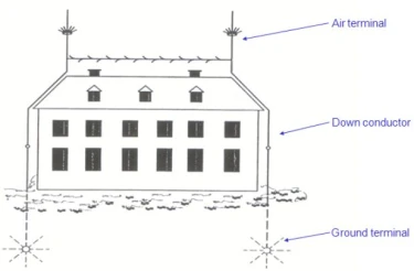
One of the purposes of the lightning protection design is to deflect and shield, which is mostly for structural protection, and also to reduce lightning electrical and magnetic fields within the building as much as possible [14- 18]. Lightning protection systems provide a safe way to relieve the lightning current in order to reduce the electrical and magnetic fields within the building without disturbing the protected connection and a preferred connection point for lightning. Such systems consist of three components mainly; air terminal, down conductor and ground terminal as illustrated in figure 1.
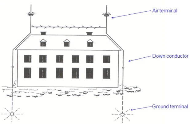
Figure 1. Traditional lightning protection system for houses. Adapted from Wiesinger and Zischank [18]
The air terminals located at convenient locations, usually the highest point in the building are used to attract the lightning. Down conductors are the connections between the air terminal and grounding terminal, and are used to transmit the lightning current to ground in the shortest way. Placement of conductors in protection systems is of particular importance. Protection vertical conductors must be located remotely in low voltage network conductors. Otherwise, in the event of any lightning strike, over voltages may be induced in the low-voltage network through induction and the voltage may both damage the devices connected to the network and pose a danger to human life. In order to minimize the electromagnetic interaction with the environment, it is necessary to ensure that the vertical protection conductors reach the grounding electrode in the shortest way.
Grounding is another important factor in protection systems. Protection system grounding must be separate from Low Voltage (LV) ground system and there should be no connection between them. Otherwise, the wave propagating from the protection system to the grounding electrode can be distributed from the LV grounding network through the network grounding electrode and instantaneous high voltages may occur in the device bodies connected to the grounding network. It is possible that these voltages pose a danger to both the device and human life.
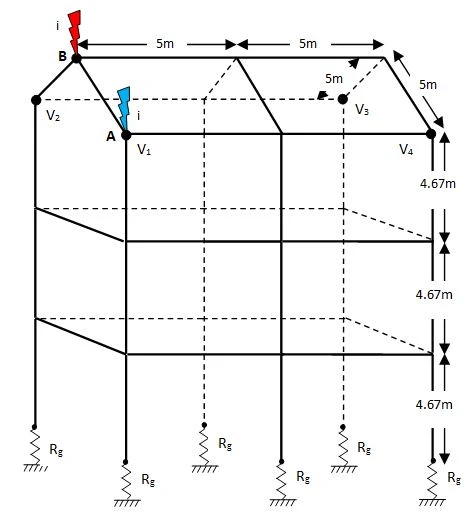
Although a three-storey building is considered in this study, the simulation method in this paper can be adopted to the other structures easily. The lightning protection system considered for this building consists of four air terminals and 2x6 grounding rods and 50mm² stranded copper wire is used for the horizontal and vertical down conductors as in [8], where single storey building with Faraday cage was considered. Two grounding rods are used at each grounding terminal and taking this publication as reference, the grounding electrodes are 2.5m long copper rods that are 30mm in diameter. Multi-conductor model of the lightning protection system is shown in figure 2.
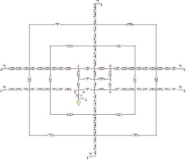
ATPDraw simulation model of the protection system for a lightning stroke at point A is shown in figure 3.
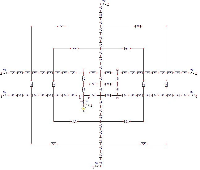
Figure 3. ATPDraw simulation models of multi-storey protection system for stroke point is A
For the stroke at point B the current source and its internal impedance is connected to point B. In the protection system, vertical conductors, called as down conductors, transfer the lightning energy into the ground. As the capacitance and inductance of a vertical conductor vary with height the surge impedance of the conductor changes with varying height [19]. Therefore, down conductors need to be characterized by nonuniform lines for a precise and comprehensive analysis. Another important issue to be considered is the velocity of the wave travelling on the line segments. Taking the measurements carried out in [20] as the reference, the propagation velocity in both horizontal and vertical conductors is taken to be the velocity of light ( ). The third factor which is important I the simulations is the simulation time step. The time step should be indicated considering the travel time of the shortest line in the system. Taking the time step Δt for the simulations as 1/100 of travel time of the shortest line in the system provides satisfactory results. In the simulations carried out in this paper, The current source used to model the lightning current is a standard 1/50 double exponential wave with 1.0 unit peak value which is represented as
  , where
  and
and 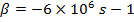 . All conductors in the protection system are represented by lossless distributed lines.
For a horizontal line segment over ground the characteristic impedance is expressed as [20, 21]:
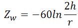 (1)
(1)
where  represents the conductor height, and
  is the radius of the conductor. This expression is used to determine the characteristic impedance of how horizontal conductors in the protection system. The characteristic impedance of a horizontal conductor is constant as
  and
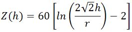
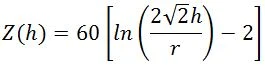
and  is constant. However, in the case of a vertical conductor the height is not constant longitudinally and hence characteristic impedance varies with respect to its height and for a proper simulation this variation should be taken into consideration. Therefore, in the simulations such configurations, the nonuniform line model with characteristic impedance changing by a logarithmic function were used [20, 22, 23]. Considering measurements and theoretical studies on characteristic impedance of nonuniform lines carried out in this literature, the variation of the characteristic impedance of the vertical conductors for the simulations carried out is expressed as [18, 20, 22]
 (2)
(2)
where  is variable and represents the change of height from the ground level, and
  is the radius of the conductor. According to this equation, for a conductor with height
  , the characteristic impedance varies from
  at ground level to
  at conductor top. In the simulation,
  uniform line sections are used for each storey to represent the nonuniform characteristic impedance and hence nine uniform line sections connected in cascade are used in total to simulate the nonuniform variation.
3.1. Lightning source and lightning path impedance
The lightning path impedance has been in concern in many studies related to the lightning surge simulations and literature search shows that several values starting from 250Ω up to 2.5kΩ have been used. In one of the earliest studies the lightning-path impedance of 400Ω was derived theoretically by assuming the lightning velocity is equal to the light velocity in free space [24]. In publications [25- 28], this impedance value was taken as reference to obtain the tower surge response. In the work done by Menemenlis [29], the surge impedance of lightning stroke was assumed to be 250Ω, which was not based on any measurement or calculation.
Higher values of lightning surge impedance were in consideration and 1000Ω to 2000Ω were recommended by Diesendorf [30]. In the measurements done by Gorin and Shkilev [31] current oscillograms were used to estimate the equivalent impedance of the lightning channel and their estimates varied from 600Ω to 2.5kΩ. Recently, based on the concepts obtained in previous studies 1000Ω has been used in many publications [28, 32, 33], which can be taken as reference and based on this investigation, 1000Ω resistance is considered as convenient for the lightning path impedance.
3.2. Grounding resistance
The grounding impedance is affected from many parameters and physical conditions such as the type of grounding electrode, its material, length of the electrode, number of electrodes, depth etc. Copper-bonded, galvanized, and stainless-steel ground electrodes are generally preferred for grounding purposes. High cost of stainless-steel rods prohibits wide span use. Therefore, copper-bonded and galvanized steel grounding rods are most common.
In protective systems, the grounding resistance must be low as much as possible to eliminate possible reflections. According to wave theory, if the termination impedance is higher than the characteristic impedance of the line which the wave travelling, a positive reflection will occur which causes an increase in the voltage. A grounding impedance of smaller or equal to 2Ω is proper value. To make grounding resistance smaller, grounding electrode should be placed deep in the ground as much as possible. Length and thickness of the electrode also effect grounding resistance. The grounding impedance can be further reduced by using several electrodes in parallel. However, if a sufficiently low grounding resistance cannot be achieved with the methods mentioned above, it is possible to obtain low values by using various chemicals. It is also very important that the ground electrode and the protective conductor are connected well. Otherwise, this will create a negative situation for grounding, since oxidation and chemical interaction that will occur over time will make the contact resistance very high.
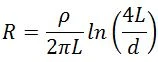
In the multi-storey building considered, the grounding is realized by copper rods. The electrode system is as described in [8]; however, it is also illustrated here also for convenience. There are several expressions that can be used for grounding resistance calculations. Strips, rods or plates are used as grounding electrodes and the expressions are different for different electrode structures [34]. In high voltage protection systems however, an electrode with a regular shape may not satisfy a proper grounding and in this case grounding grids are used. If the grounding is done by a rod electrode the resistance of grounding electrode is calculated by the expression [34]:
 (3)
(3)
In the simulation presented in the paper, the lightning wave is normalized such that its amplitude to be  for simplification. The results can be easily converted to the real values by considering the amplitude of the lightning wave by multiplying normalized values by real amplitude. Several measurements have been carried out in real environment to identify the peak values of the lightning currents in different places [36, 37]; and in these publications, median peak currents for the first and subsequent strokes were measured as
  and
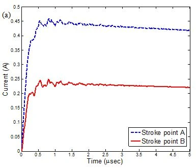
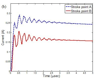
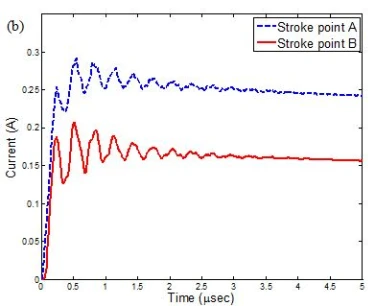
and  , respectively. The injected lightning current and the current waveform at down conductor at stroke point obtained by ATP-EMTP simulation are shown in figure 4.

Figure 4. a) 1/50 lightning current waveform, b) Currents at down conductor at stroke point A, and at stroke point B
Changes of the currents at down conductor from third storey to first storey at stroke point A, and stroke point B are shown in figure 5 when lightning-path impedance is Zi=1kΩ . Note that the values of the currents are for normalized lightning current with amplitude 1A
 .
.
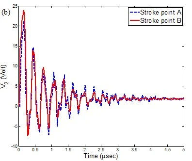
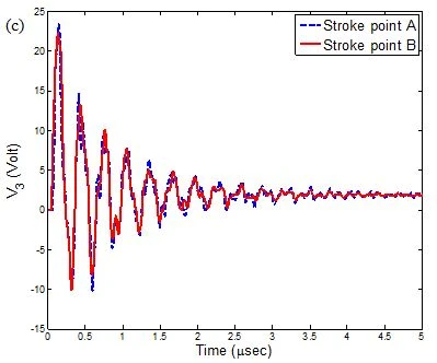
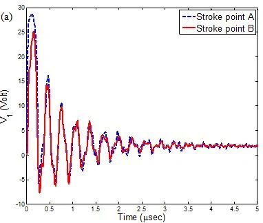
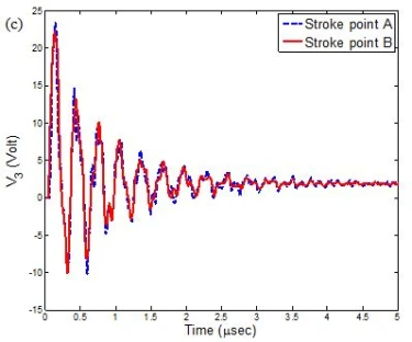
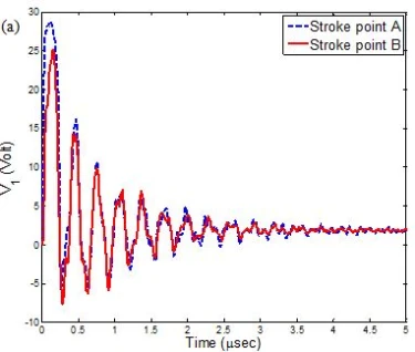
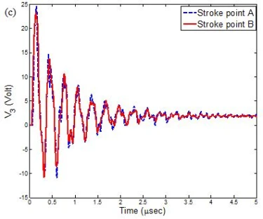
Changes of the voltages at critical points for  value of the grounding resistance are given in figure 6 when lightning-path impedance is
  . Note that the values of the voltages are for normalized lightning current with amplitude
  .
.
The lightning-path impedance is taken to be  and peak values of the voltages at critical points obtained from simulations are given in table 1. As seen from the table 1, the maximum value of the voltages measured at stroke point A is
  . For a lightning current with
  amplitude it corresponds to the value
  for this condition. The maximum value of the voltages is
  at stroke point B and for a lightning current with
  amplitude it corresponds to the value
  .
.

Figure 6. (a),(b),(c),(d) Voltages at critical points, for stroke point is A, for stroke point is B
a
4.1. Investigation the effect of radius of conductors
The effect of radius of horizontal and down conductors on the surge response is investigated for two different values of conductor radius. As a first case the cross section area of the conductors is taken to be 50mm², as in the previous section and the results are tabulated in table 1. As a second case the cross section of the conductor is decreased by half and 25mm² is used for the conductor cross section. Source impedance is Z_i=1kΩ and each grounding resistance is 12Ω in all cases. The effect of the conductor radius on the resulting voltages and currents is investigated and the voltages at critical points for stroke point A and B are illustrated in figure 7. The recorded peak values of the voltages at critical points are tabulated in table 2 and changes of the voltages at critical points for conductor cross section by reducing from 50mm² to 25mm² are demonstrated in table 3. As it is seen from the figure and tables when the conductor radius is increased multiply by two the voltage decreases %5, averagely. However, the current flowing through the conductors remains almost same.
4.2. Investigation the effect of radius of conductors
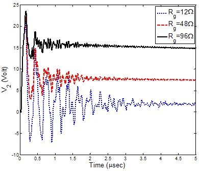
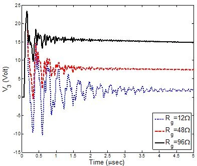
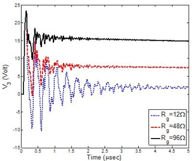
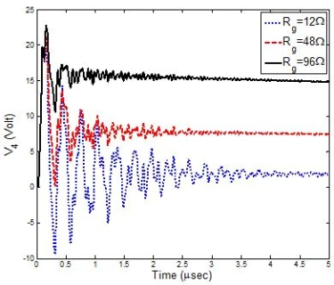
The voltage waveforms at stroke point A for different values of the grounding resistance ( ) are illustrated in figure 8.

Figure 8. (a),(b),(c),(d) Voltages at critical points for different values of the grounding resistance Rg = 12, 48 and 96 Ω
a
The peak values of the voltages at critical points for 1A peak lightning current for all values of the grounding resistance are given in table 4. As it can be seen from the figures, the value of grounding resistance have small effect on the first peak of the voltage which is due to much lower grounding resistance values compared with surge impedance of the vertical conductor, which is 300.2Ω. However, voltage waves reduce more rapidly for small values of the grounding resistance.
In this study, a protection system for a three-storey building is modeled and simulated using distributed line models for protection system conductors in ATP-EMTP. Distributed line modeling is used for the protective system and the down conductors are modeled by considering non-uniform variation of the characteristic impedance that varies with height. The currents in some critical conductors and the voltages at some critical points following the lightning stroke for various grounding resistances, and different conductor cross section are obtained. The conventional lightning parameters required for structural protection such as lightning peak current, current rise time and current duration are determined.
1 R.S. Velazquez, V. Gerez, D. Mukhedkar, and Y. Gervais, IEEE Transactions on Industry Applications IA-18(3) (1982) 252. https://doi.org/10.1109/TIA.1982.4504069
2 A. Sowa, IEEE International Symposium on Electromagnetic Compatibility, Cherry Hill, NJ (1991) 103.
3 U. Kumar, V. Hegde, P.B. Darji, IET Sci. Meas. Technol. 1(5) (2007) 225. http://dx.doi.org/10.1049/iet-smt:20060051
4 G. Maslowski, V.A. Rakov, et al., IEEE Trans. On Electromagnetic Compatibility 57(3) (2015) 425. https://doi.org/10.1109/TEMC.2014.2382556
5 R. Araneo, S. Celozzi, A. Tatematsu, F. Rachidi, IEEE Transactions on Electromagnetic Compatibility 57(3) (2015) 397. http://dx.doi.org/10.1109/TEMC.2014.2377776
6 M. Rahman, M.O. Goni, K. Mitobe, M. Suzuki, International Conference on Electrical and Computer Engineering, ICECE 2008 (2008) 694. http://dx.doi.org/10.1109/ICECE.2008.4769298
7 A. Tatematsu, F. Rachidi, M. Rubinstein, International Symposium on Electromagnetic Compatibility, Tokyo, Japan (2014) 386.
8 M.S. Mamiş, C. Keleş, M. Arkan, R. Kaya, EEUG Conference, Zwickau, Germany (2012) 1.
9 M.S. Mamiş, C. Keleş, M. Arkan, R. Kaya, IET Gener. Transm. Distrib. 10(4) (2016) 1016. http://dx.doi.org/10.1049/iet-gtd.2015.0794
10 V. Hegde, V. Shivanand, IEEE Transactions on Electromagnetic Compatibility 57(3) (2015) 418. http://dx.doi.org/10.1109/TEMC.2015.2399512v
11 C.H. Lee, C.N. Chang, J.A. Jiang, IEEE Transactions on Industry Applications 51(6) (2015) 4882. http://dx.doi.org/10.1109/TIA.2015.2399618
12 F. Aslani, M. Yahyaabadi, B. Vahidi, IET Sci. Meas. Technol. 12(8) (2018) 958. https://doi.org/10.1049/iet-smt.2018.5002
13 Anonymous, Alternative Transient Program (ATP), URL: http://www.emtp.org/ (Accessed date: April 30, 2024) (2004).
14 M. Szczerbiński, Journal of Electrostatics 48(2) (2000) 145. https://doi.org/10.1016/S0304-3886(99)00062-5
15 V.A. Rakov, M.A. Uman, Lightning: Physics and Effects, Cambridge University Press (2003) 687 p.
16 V.A. Rakov, X International Symposium on Lightning Protection, Curitiba, Brazil (2009).
17 G.L. Amicucci, B. D’Elia, Journal of Electrostatics 60(2–4) (2004) 247. http://dx.doi.org/10.1016/j.elstat.2004.01.015
18 J. Wiesinger, W. Zischank, Handbook of Atmospheric Electrodynamics II (1995) 33.
19 P.C.A. Mota, M.L.R. Chavez, J.R. Camacho, Power Quality (2016) 340.
20 T. Hara, O. Yamamoto, IEE Proc.-Genre. Transm. Distrib. 143(3) (1996) 283. https://doi.org/10.1049/IP-GTD%3A19960289
21 W.A. Chisholm, Y.L. Chow, K.D. Srivastava, IEEE Transactions on Power Apparatus and Systems 102(9) (1983) 3232. http://dx.doi.org/10.1109/TPAS.1983.318134
22 A. Ametani, Y. Kasai, IEE Proc.-Gener. Transm. Distrib. 141(4) (1994) 339. https://doi.org/10.1049/IP-GTD%3A19949988
23 P. Gómez, International Conference on Power Systems Transients, (IPST2015), Cavtat, Croatia (2015).
24 L.V. Bewley, Traveling Waves on Transmission Systems, Dover Publications, N.Y. (1963) 543p.
25 M. Ishii, T. Kawamura, T. Kouno, E. Ohsaki, K. Shiokawa, K. Murotani, T. Higuchi, IEEE Transactions on Power Delivery 6 (3) (1991) 1327. https://doi.org/10.1109/61.85882
26 M.E. Almeida, M.T. Correia De Barros, IEE Proc. Gener. Transm. Distrib. 141 (6) (1994) 637.
27 Y. Baba, M. Ishii, IEEE Trans. on Power Delivery 16(2) (2001) 324. http://dx.doi.org/10.1109/PESS.2001.970000
28 A. Ametani, T. Kawamura, IEEE Trans. on Power Delivery 20(2) (2005) 867. http://dx.doi.org/10.1109/TPWRD.2004.839183
29 C. Menemenlis, Z.T. Chun, IEEE Transactions on Power Apparatus and Systems 101(4) (1982) 833. https://doi.org/10.1109/TPAS.1982.317148
30 W. Diesendorf, Insulation co-ordination in high voltage electric power systems, London, U.K., Butterworths (1974).
31 B.N. Gorin, A.V. Shkilev, Elektrichestvo 8 (1984) 64 [in Russian].
32 M. Kizilcay, EEUG Meeting 2015, European EMTP-ATP Conference, Grenoble, France (2015) 113.
33 A. Mackow, P. Malicki, M. Kizilcay, EEUG Meeting 2015, European EMTP-ATP Conference, Grenoble, France (2015) 127.
34 A.S. Pabla, Grounding in electric power distribution. Tata McGraw Hill Company Limited, 4th edition (1997).
35 R.B. Carpenter, J.A. Lanzoni, Designing for a low resistance earth interface (Grounding), An LEC Publication (2007).
36 S. Visacro, A. Soares, M. Aurélio, O. Schroeder, L.C.L. Cherchiglia, V.J. de Sousa , J. Geophys. Res. 109(D1) D01105-1. http://dx.doi.org/10.1029/2003JD003662
37 J. Takami, S. Okabe, Observational results of lightning current on transmission towers. IEEE Trans. Power Del. 22(1) (2007) 547.
M.S. Mamiş, C. Keleş, ATP-EMTP simulation of lightning protection system for multi-storey building, UNEC J. Eng. Appl. Sci. 4(1) (2024) 43-54 https://doi.org/10.61640/ujeas.2024.0504
Anyone you share the following link with will be able to read this content:
This article is licensed under the Creative Commons Attribution ( CC BY 4.0 ) License, which permits unrestricted use, distribution, and reproduction in any medium, provided the original author and source are credited.


R.S. Velazquez, V. Gerez, D. Mukhedkar, and Y. Gervais, IEEE Transactions on Industry Applications IA-18(3) (1982) 252. https://doi.org/10.1109/TIA.1982.4504069
A. Sowa, IEEE International Symposium on Electromagnetic Compatibility, Cherry Hill, NJ (1991) 103.
U. Kumar, V. Hegde, P.B. Darji, IET Sci. Meas. Technol. 1(5) (2007) 225. http://dx.doi.org/10.1049/iet-smt:20060051
G. Maslowski, V.A. Rakov, et al., IEEE Trans. On Electromagnetic Compatibility 57(3) (2015) 425. https://doi.org/10.1109/TEMC.2014.2382556
R. Araneo, S. Celozzi, A. Tatematsu, F. Rachidi, IEEE Transactions on Electromagnetic Compatibility 57(3) (2015) 397. http://dx.doi.org/10.1109/TEMC.2014.2377776
M. Rahman, M.O. Goni, K. Mitobe, M. Suzuki, International Conference on Electrical and Computer Engineering, ICECE 2008 (2008) 694. http://dx.doi.org/10.1109/ICECE.2008.4769298
A. Tatematsu, F. Rachidi, M. Rubinstein, International Symposium on Electromagnetic Compatibility, Tokyo, Japan (2014) 386.
M.S. Mamiş, C. Keleş, M. Arkan, R. Kaya, EEUG Conference, Zwickau, Germany (2012) 1.
M.S. Mamiş, C. Keleş, M. Arkan, R. Kaya, IET Gener. Transm. Distrib. 10(4) (2016) 1016. http://dx.doi.org/10.1049/iet-gtd.2015.0794
V. Hegde, V. Shivanand, IEEE Transactions on Electromagnetic Compatibility 57(3) (2015) 418. http://dx.doi.org/10.1109/TEMC.2015.2399512v
C.H. Lee, C.N. Chang, J.A. Jiang, IEEE Transactions on Industry Applications 51(6) (2015) 4882. http://dx.doi.org/10.1109/TIA.2015.2399618
F. Aslani, M. Yahyaabadi, B. Vahidi, IET Sci. Meas. Technol. 12(8) (2018) 958. https://doi.org/10.1049/iet-smt.2018.5002
Anonymous, Alternative Transient Program (ATP), URL: http://www.emtp.org/ (Accessed date: April 30, 2024) (2004).
M. Szczerbiński, Journal of Electrostatics 48(2) (2000) 145. https://doi.org/10.1016/S0304-3886(99)00062-5
V.A. Rakov, M.A. Uman, Lightning: Physics and Effects, Cambridge University Press (2003) 687 p.
V.A. Rakov, X International Symposium on Lightning Protection, Curitiba, Brazil (2009).
G.L. Amicucci, B. D’Elia, Journal of Electrostatics 60(2–4) (2004) 247. http://dx.doi.org/10.1016/j.elstat.2004.01.015
J. Wiesinger, W. Zischank, Handbook of Atmospheric Electrodynamics II (1995) 33.
P.C.A. Mota, M.L.R. Chavez, J.R. Camacho, Power Quality (2016) 340.
T. Hara, O. Yamamoto, IEE Proc.-Genre. Transm. Distrib. 143(3) (1996) 283. https://doi.org/10.1049/IP-GTD%3A19960289
W.A. Chisholm, Y.L. Chow, K.D. Srivastava, IEEE Transactions on Power Apparatus and Systems 102(9) (1983) 3232. http://dx.doi.org/10.1109/TPAS.1983.318134
A. Ametani, Y. Kasai, IEE Proc.-Gener. Transm. Distrib. 141(4) (1994) 339. https://doi.org/10.1049/IP-GTD%3A19949988
P. Gómez, International Conference on Power Systems Transients, (IPST2015), Cavtat, Croatia (2015).
L.V. Bewley, Traveling Waves on Transmission Systems, Dover Publications, N.Y. (1963) 543p.
M. Ishii, T. Kawamura, T. Kouno, E. Ohsaki, K. Shiokawa, K. Murotani, T. Higuchi, IEEE Transactions on Power Delivery 6 (3) (1991) 1327. https://doi.org/10.1109/61.85882
M.E. Almeida, M.T. Correia De Barros, IEE Proc. Gener. Transm. Distrib. 141 (6) (1994) 637.
Y. Baba, M. Ishii, IEEE Trans. on Power Delivery 16(2) (2001) 324. http://dx.doi.org/10.1109/PESS.2001.970000
A. Ametani, T. Kawamura, IEEE Trans. on Power Delivery 20(2) (2005) 867. http://dx.doi.org/10.1109/TPWRD.2004.839183
C. Menemenlis, Z.T. Chun, IEEE Transactions on Power Apparatus and Systems 101(4) (1982) 833. https://doi.org/10.1109/TPAS.1982.317148
W. Diesendorf, Insulation co-ordination in high voltage electric power systems, London, U.K., Butterworths (1974).
B.N. Gorin, A.V. Shkilev, Elektrichestvo 8 (1984) 64 [in Russian].
M. Kizilcay, EEUG Meeting 2015, European EMTP-ATP Conference, Grenoble, France (2015) 113.
A. Mackow, P. Malicki, M. Kizilcay, EEUG Meeting 2015, European EMTP-ATP Conference, Grenoble, France (2015) 127.
A.S. Pabla, Grounding in electric power distribution. Tata McGraw Hill Company Limited, 4th edition (1997).
R.B. Carpenter, J.A. Lanzoni, Designing for a low resistance earth interface (Grounding), An LEC Publication (2007).
S. Visacro, A. Soares, M. Aurélio, O. Schroeder, L.C.L. Cherchiglia, V.J. de Sousa , J. Geophys. Res. 109(D1) D01105-1. http://dx.doi.org/10.1029/2003JD003662
J. Takami, S. Okabe, Observational results of lightning current on transmission towers. IEEE Trans. Power Del. 22(1) (2007) 547.