UNEC Journal of Engineering and Applied Sciences Volume 3, No 2, pages 5-13 (2023) Cite this article, ![]() 5292 https://doi.org/10.61640/ujeas.2023.1201
5292 https://doi.org/10.61640/ujeas.2023.1201
A solar collector is a device that assists in converting solar radiation into thermal one. The parabolic trough collector (PTC) is regarded as an exceptional solar collector for medium temperature (150–400 °C) heat demand. Nowadays, enhancing thermal performance of Solar PTC has attracted the many researchers. Along with other components including parabolic mirrors, metal support structure, and tracking unit assembly, the absorber tube also known as the receiver tube or heat collection element, is one of the primary functioning parts of a solar PTC. The main reason this is that, the efficiency and performance of the PTC system highly depend on the design and effectiveness of this absorber tube. Therefore, numerous methods, including half-insulation receivers, cavity receivers, vacuum outer shells, baffles, artificially roughened sinks, selective coatings, etc., were used in an effort to enhance the heat transfer potential in the receiver tube part of a solar PTC [1]. In typical PTC, lower part of the absorber tube receives concentrated solar irradiation which results in high temperatures, thermal stress, and tube deformation. To tackle these issues, rotating the absorber tube at a certain frequency is suggested in order to reduce the high surface temperature and maximize solar energy absorption [2]. Thermal performance enhancement for absorber tube of solar PTC is conducted with three dimensional model using ANSYS FLUENT 18.2. Using the FVM, all of the numerical results were achieved. Results indicate that employing one of the suggested receiver for parabolic trough solar collectors over a simple one might boost thermal performance by 23.1% [3]. Temperature distribution of glass covered receiver tube is investigated by studying the effect of uniform heat flux on parabolic through collector. Due to the absence of comprehensive research to analyze three dimensional temperature variation of receiver tube of PTC [4]. A comparative study is conducted to evaluate the effect of size of various absorber tubes for reflector surface of parabolic trough reflector. Results showed that, reference system obtained 77 to 78% efficiency when the efficiency is increased to 79 and 81% by second absorber tube [5]. Helically convex structure design is proposed and analyzed with Monte Carlo ray tracing method, the Finite Volume Method. Results indicate that, with the assistance of changing the receiver into this design can optimize heat transfer and fluid properties [6]. Rectangular cavity receiver of Solar PTC was investigated with the help of smooth and corrugated cavity tube by [7]. In that study, thermal performance of cavity receiver tube is evaluated by using three different working fluids. Research indicates that, rectangular cavity receiver with corrugated tube significantly enhance efficiency of Solar PTC comparing to smooth tube. Thermal performance of parabolic trough collector (PTC) system is analyzed numerically with ANSYS-CFX CFD software [8]. CFD simulation of helical screw tape (HST) and CuO/oil nanofluid is carried out to enhance of heat flux absorption by the absorber tubes. The results show that applying the CuO/oil nanofluid may improve the PEC by 57.3–70.8, 68.7~86.4, and 83.4~105.9% for volume fractions of 1, 2, and 3%, respectively [9]. This study is also carried out with the assistance of conjugate heat transfer and fluid flow interfaces. Electric analog circuit for the thermal analysis of CPC collectors which is used in the articles [10-13] can also be applied to Solar PTC collector.
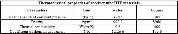
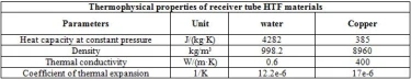
Water is a useful HTF material for low-temperature solar applications applications due to its boiling point is about 100 °C and thermal properties of water is shown in table 1.
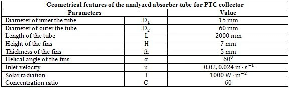
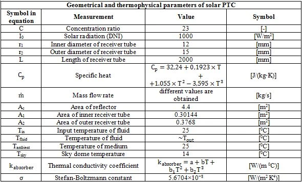
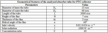
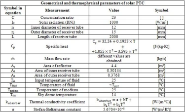
Geometrical features and thermophysical properties of the analyzed absorber tube for PTC collector are mentioned in table 2.
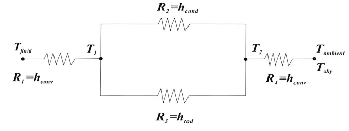
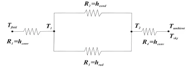
2.1 Electrical analog methods for heat loss of absorber tube.
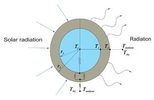
Electro analog method was used in stationary state to solve thermal physical processes figure 1 and 2.
The research of PTC solar concentrator is based on the theory proposed by many authors. It has been determined that a mathematical model utilized for CPC solar collectors can also be applied to PTC. [10-13]. Solar radiation is received through the absorber tube and transfers heat to the heat transfer fluid.
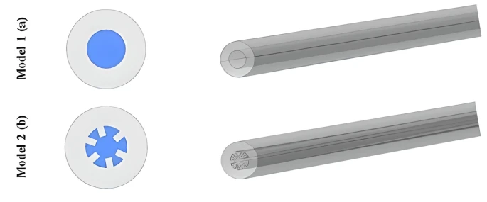
Figure 3. (a) A schematic of the receiver tube structure, (b) the schematic of the considered tube inner helical axial fins
 (1)
(1)
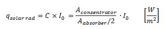
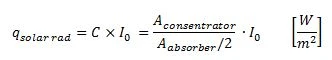
here  - is total solar heat flux density transmitted to the absorber pipe [W/m²], C-concentration coefficient
  , I0- solar radiation constant [W/m²],
  - the surface of the concentrator [m²],
  - surface area of the absorber tube [m²].
The surface of the concentrator is equal to the concentration coefficient multiplied by the half surface of the absorber tube, because concentrated sunlight falls on half of the absorber tube is given (2). The total energy flow transferred to the absorber is determined by (3):
 (2)
(2)
 (3)
(3)
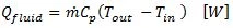
The following (4) is given for the heat transfer fluid flowing through the absorber:
 (4)
(4)
here  – fluid energy flow [W],
  –mass flow rate [kg/s],
  – specific heat capacity of liquid,
  – initial temperature of liquid,
  – outlet temperature of liquid at the end of absorber.
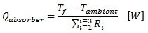
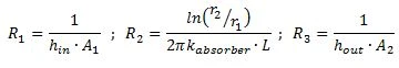
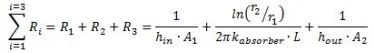
The consumption of conductive heat power and radiation power of the absorber is determined by (5) and (6):
 (5)
(5)
 (6)
(6)
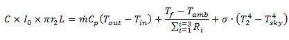
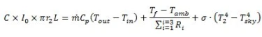
Solar energy is used to heat the liquid and heat the absorber (7). The absorber has conductive, convective and radiation consumption capacities.
 (7)
(7)
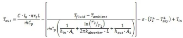
From (7), we can determine the following equation and we can obtain the temperature of the heat transfer fluid exiting the absorber tube (12).
 (8)
(8)
 (9)
(9)
 (10)
(10)
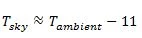
Considering the thermal exchange that occurs between buildings and the environment, in the absence of data to calculate sky temperature, this can be easily calculated using ISO 13790, as demonstrated by the equations shown below [13-15].
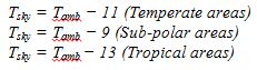
The ISO 13790 standard allows the sky temperature to be simply calculated in order to determine the energy required to heat residential and non-residential structures.
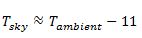 (11)
(11)
Summarizing the above (8), (9), (10), (11) it is possible to form the following (12).
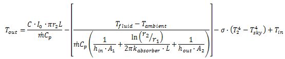 (12)
(12)
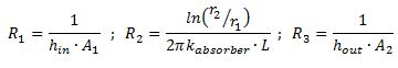
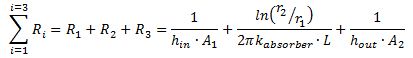
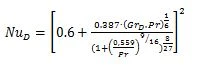
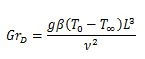
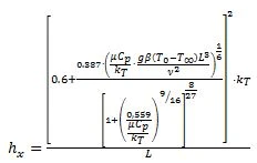
here hin and hout the internal and external convective heat transfer coefficient of the absorber changes depending on the Nusselt (NuD), Grassgoff (GrD) and Prandalt (Pr) numbers. Taking this into account, it is calculated based on (13), (14), (15).
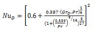 (13)
(13)
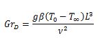 (14)
(14)
 (15)
(15)
Using these (13), (14), (15) and (16), (17) is determined and the values of hin and hout are obtained in the case of giving the required values.
 (16)
(16)
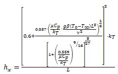 (17)
(17)
As a basis, the above equations are taken from articles and literature [10-{ref:20}].
In this study, the solar PTC system with water with specific characteristics was used to transfer radiation into heat energy. Firstly, a geometric 3D model was built in COMSOL Multiphysics by using Heat Transfer in Solid and Fluid and Laminar Flow interfaces. Boundary conditions were introduced into the program (given in table 3) and the following results were obtained (see figures 4-7) depending on the Cut Line 3D.
Distribution of receiver tube temperature
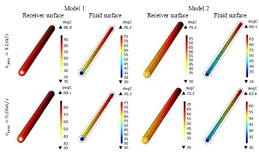
Figure 4 shows the temperature distribution of absorber tube of solar PTC made of copper materials. The absorber tube is typically made of a highly efficient material with good thermal conductivity. Therefore, copper is chosen for receiver tube materials. Water with the initial temperature 30°C is utilized as heat transfer fluid. In that figure, it is possible to see the maximum, minimum and average values of surface temperature of receiver tubes at the velocity 0.2 m/s, 0.24 kg/sec.
Cut Line 3D is used for dataset to create lines through 2D or 3D geometries to visualize along the line. Along this line temperature variation is determined.
In figure 5 for the velocity (0.2 kg/sec, 0.24 kg/sec the inlet and outlet velocities were investigated and determined. Velocity of HTF is not depended on the material of receiver tube. However, it is mainly relied on temperature and geometric shape of receiver tube. Here temperature variation is given in (figure 6) and geometric shape of absorber tube is not change. For that reason, velocity magnitude changes according to inlet velocity (figure 5 and 7).
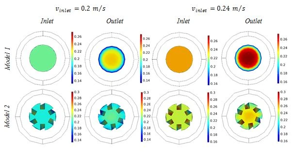
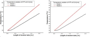
Figure 6. Temperature variation of HTF of two receiver tube models at different velocities
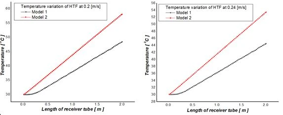
In the figure 6 it is possible to examine that HTF in model 2 receiver tube is relatively hotter comparing to model 1 receiver tube made. It can be seen in the picture (figure 4) that the temperature on the surface of model 2 receiver tube is relatively low, this means energy loss to the medium is less than other receiver and it can transfer more energy to HTF. See figure 6.
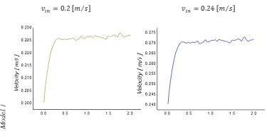
Figure 7. Variation of the velocity of HTF of Model 1 and Model 2 in 0.2 m/s and 0.24 m/s 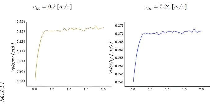
It can be seen in figure 7. Velocity magnitude of HTF in model 2 significantly increased in middle of receiver tube. This is why, model 2 receiver tube is mechanically twisted into 600, this is in turn affected to geometric parameters of absorber tube.
When mass velocity of heat transfer fluid Water which is flowing through the Model 1 receiver tube of PTC is 0.2 m/s and 0.24 m/s, velocity along the length of the receiver tubes changed from 0.2 m/s to 0.27 m/s and outlet temperature of HTF for Model 1 is 48.49 °C, 44.49 °C respectively to the velocity. For Model 2 receiver tube, velocity of HTF is changed from 0.2 m/s to 0.22 m/s. Outlet temperature of HTF is reached to 58.15 °C and 53.43 °C in 0.2 m/s and 0.24 m/s velocity respectively. From these analyses, it can be concluded that absorber tube with inner helical axial fins showed better performance in two various velocities compared to simple receiver. Changing the mass flow rate of HTF has significant influence on the surface and fluid temperature.
1 G. Kumaresan, P. Sudhakar, R. Santosh, R. Velraj, Renewable and Sustainable Energy Reviews 77 (2017) 1363. https://doi.org/10.1016/j.rser.2017.01.171
2 A.M. Norouzi, M. Siavashi, M.H. Khaliji Oskouei, Renewable Energy 145 (2020) 569. https://doi.org/10.1016/j.renene.2019.06.027
3 M. Zaboli, S.S.M. Ajarostaghi, S. Saedodin and M.S. Pour, Applied Sciences 11(16) (2021) 7423. https://doi.org/10.3390/app11167423
4 S. Marrakchi, Z. Leemrani, H. Asselman, A. Aoukili, A. Asselman, Procedia Manufacturing 22 (2018) 773. https://doi.org/10.1016/j.promfg.2018.03.110
5 C.K. Hsieh, Solar Energy 27 (1981) 19. https://doi.org/10.1016/0038-092X(81)90016-5
6 A. Rabl, Solar Energy 18 (1976) 93. https://doi.org/10.1016/0038-092X(76)90069-4
7 N. Ortega, O. García-Valladares, R. Best, V.H. Gómez, Renew. Energy 33 (2008) 2064. https://doi.org/10.1016/j.renene.2007.11.016
8 H. Shoeibi, A. Jarrahian, M. Mehrpooya, E. Assaerh, M. Izadi, F. Pourfayaz, Energies 16(1) (2023) 287. https://doi.org10.3390/en16010287
9 B.S. Reddy, K.H. Reddy, Thermal Enginering Data Handbook, I.K. International Publishing House Pvt. Ltd. (2007) 272p.
10 F. Kreith, W,Z. Black, Basic Heat Transfer. Harper and Row (1980) 556p.
11 J.S. Akhatov, Kh.S. Ahmadov, Applied Solar Energy 58(6) (2022) 889. https://doi.org/10.3103/S0003701X22060032
12 S.A. Boltaev, Kh.S. Akhmadov, U.R. Gapparov, M.K. Kurbanov, D.S. Saidov, Applied Solar Energy 58(1) (2022) 116. https://doi.org/10.3103/S0003701X22010042
13 J.S. Akhatov, K.A. Samiev, U.B. Sharopov, Kh.S. Ahmadov, A.S. Khalimov, E.T. Juraev, Kh.F. Sayfieva, T.I. Juraev, Problems of Information technologies and Energetics, Tashkent, Uzbekistan 4 (2021) 45.
14 A.A. Kuchkarov, A.E. Khaitmukhamedov, A.O. Shukurov, M.Kh. Dekhkonova, M.R. Mukhiddinov, Applied Solar Energy 56(1) (2020) 42. http://dx.doi.org/10.3103/S0003701X20010089
15 A. Abdurakhmanov, A.A. Kuchkarov, M.A. Mamatkosimov, Yu.B. Sobirov, and J.Z. Akhadov. Applied Solar Energy 52(2) (2016) 137. https://doi.org/10.47494/mesb.2021.18.901
J.S. Akhatov, Kh.S. Akhmadov, N.I. Juraboyev, Thermal performance enhancement in the receiver part of solar parabolic trough collectors, UNEC J. Eng. Appl. Sci. 3(2) (2023) 5-13 https://doi.org/10.61640/ujeas.2023.1201
Anyone you share the following link with will be able to read this content:
This article is licensed under the Creative Commons Attribution ( CC BY 4.0 ) License, which permits unrestricted use, distribution, and reproduction in any medium, provided the original author and source are credited.


G. Kumaresan, P. Sudhakar, R. Santosh, R. Velraj, Renewable and Sustainable Energy Reviews 77 (2017) 1363. https://doi.org/10.1016/j.rser.2017.01.171
A.M. Norouzi, M. Siavashi, M.H. Khaliji Oskouei, Renewable Energy 145 (2020) 569. https://doi.org/10.1016/j.renene.2019.06.027
M. Zaboli, S.S.M. Ajarostaghi, S. Saedodin and M.S. Pour, Applied Sciences 11(16) (2021) 7423. https://doi.org/10.3390/app11167423
S. Marrakchi, Z. Leemrani, H. Asselman, A. Aoukili, A. Asselman, Procedia Manufacturing 22 (2018) 773. https://doi.org/10.1016/j.promfg.2018.03.110
C.K. Hsieh, Solar Energy 27 (1981) 19. https://doi.org/10.1016/0038-092X(81)90016-5
A. Rabl, Solar Energy 18 (1976) 93. https://doi.org/10.1016/0038-092X(76)90069-4
N. Ortega, O. García-Valladares, R. Best, V.H. Gómez, Renew. Energy 33 (2008) 2064. https://doi.org/10.1016/j.renene.2007.11.016
H. Shoeibi, A. Jarrahian, M. Mehrpooya, E. Assaerh, M. Izadi, F. Pourfayaz, Energies 16(1) (2023) 287. https://doi.org10.3390/en16010287
B.S. Reddy, K.H. Reddy, Thermal Enginering Data Handbook, I.K. International Publishing House Pvt. Ltd. (2007) 272p.
F. Kreith, W,Z. Black, Basic Heat Transfer. Harper and Row (1980) 556p.
J.S. Akhatov, Kh.S. Ahmadov, Applied Solar Energy 58(6) (2022) 889. https://doi.org/10.3103/S0003701X22060032
S.A. Boltaev, Kh.S. Akhmadov, U.R. Gapparov, M.K. Kurbanov, D.S. Saidov, Applied Solar Energy 58(1) (2022) 116. https://doi.org/10.3103/S0003701X22010042
J.S. Akhatov, K.A. Samiev, U.B. Sharopov, Kh.S. Ahmadov, A.S. Khalimov, E.T. Juraev, Kh.F. Sayfieva, T.I. Juraev, Problems of Information technologies and Energetics, Tashkent, Uzbekistan 4 (2021) 45.
A.A. Kuchkarov, A.E. Khaitmukhamedov, A.O. Shukurov, M.Kh. Dekhkonova, M.R. Mukhiddinov, Applied Solar Energy 56(1) (2020) 42. http://dx.doi.org/10.3103/S0003701X20010089
A. Abdurakhmanov, A.A. Kuchkarov, M.A. Mamatkosimov, Yu.B. Sobirov, and J.Z. Akhadov. Applied Solar Energy 52(2) (2016) 137. https://doi.org/10.47494/mesb.2021.18.901