UNEC Journal of Engineering and Applied Sciences Volume 3, No 1, pages 45-68 (2023) Cite this article, ![]() 2473 https://doi.org/10.61640/ujeas.2023.0508
2473 https://doi.org/10.61640/ujeas.2023.0508
Although there are lots of researches going on for the alternative power source, IC engine is expected to remain as primary source of power for automobile in the foreseeable future. There are still different engine components remaining to be studied for fuel efficiency, better performance and reduced harmful emissions.
The maximum thermal efficiency of modern gasoline is limited by different losses that occur in the engine. In an IC engine, major sources of losses include thermal loss, pumping loss, mechanical friction loss etc. Power cylinder components are the major sources of frictional loss in IC engine. These components include: piston, piston rings, liners, connecting rod and piston pin [1]. Friction loss between the piston ring and cylinder liner contributes significantly to the power loss of IC engines. It has been projected that the piston ring assembly is generally the greatest contributors to the engine friction losses, accounts for 20-30% of the total friction losses [2, 3].
Therefore, many researchers have been paid more attention to reduce the friction losses of piston ring-cylinder liner assembly to enhance IC engines performance [4-7]. The frictional behavior between ring-liner assembly is extensively governed by the tribological phenomenon occurred between them [8]. The ring-liner assembly is the most problematical tribological components of IC engine to investigate, due to the large variation of lubrication regimes in one single stroke of the piston [9]. Moreover, tribological behavior of this assembly is also significantly influenced by many factors, such as ring geometry, ring elastic characteristics cylinder liner surface, surface topography and oil properties [10, 11].
Various researches have been carried out to understand the influence of those factors on lubrication regimes between ring and liner through numerical and experimental investigations. Furuma et al studied the oil film thickness experimentally and compared with theoretical calculation [12]. Ma et al. have done compressive analysis of ring pack lubrication using flow-continuity algorithm and obtained that the tribological performance of the compression ring was significantly affected by the cylinder liner surface [13]. Akalin et al. studied ring-liner friction in mixed lubrication by using Reynolds equation and asperity contact approach to simulate frictional performance of ring-liner contact [14]. Mufti et al. performed experimental study on the piston assembly friction of a gasoline engine using the indicated mean effective pressure [15]. Forero J et al analyzed the influence of the geometrical profile of the top ring on the tribological characteristics, such as, friction force, lubricant film thickness and pressure, and power loss of a diesel engine. They concluded the changes in geometric profile of the top compression ring has significant effect on reducing the hydrodynamic friction force at the cylinder liner interface and ring surface [16].
Consequently, various experimental and theoretical investigations were carried out to study the effect of surface texture on the lubrication performance of top ring-liner system. These studies mainly focused on surface texturing applied on piston ring and cylinder liner by using different surface processing technologies. Kligerman Y, et al suggested that partial dimple must be textured on the flat compression ring to attain the minimum friction and oil consumption [17]. Zavos et al. studied the effect of dimple shapes on the frictional force of flat piston ring under various operating conditions. They suggested that the higher friction reduction was obtained when the rectangular dimples were textured on the surface of piston ring [18, 19]. Similarly, different researches have been carried out to study the effect of simples texturing on cylinder liner for friction and wear reduction. Mohamad et al. studied the effect of groove texturing with suitable shape and size on the cylinder liner of flat piston-ring liner system. They recommended that the textured groove on the cylinder surface lowered the frictional force between ring liner assembly [20, 21]. Likewise, Gu et al. examined effect of groove distribution on the liner of a barrel shaped top ring-liner assembly and found that the fully textured liner has lower wear and friction loss in comparison to partial groove on liner surface [22]. In the same way, various experimental studies have been carried out to improve the performance of common lubricants by incorporating nanoparticles additives. These studies confirmed that the mixing of nanoparticles in the common engine oil improve the lubricating properties and hence appreciably condenses the friction and wear rate of ring and liner assembly. Zin et al. studied the effect of mixing of Copper (Cu) nanoparticles as an additive in common lubrication oil and reported that tribological properties of the oil were enhanced. In this study they also revealed that the friction and wear reduction rate was significantly dependent on the size of nanoparticles [23]. Wan et al. experimentally studied the performance of boron nitride nanoparticle merged lubricant oil and recommended that lubricant oil with a small amount of boron nitride nanoparticles significantly enhances the tribological performance [24]. Laad M et al. reported that the addition of 0.3% by weight of TiO2 nanoparticles in the common lubricating oil reduced the friction co-efficient by 86% as compared to the oil without TiO2 nanoparticles [25].
The aforementioned studies demonstrated that there have been very few reports regarding the effect of compression ring crown height on the performance internal combustion engine. Hence, we were motivated to study the effect of compression ring crown height on film thickness, friction force, wear and power losses of four stroke petrol engine.
The analysis on the effect of compression ring crown height on performance of four stroke petrol engine was developed using matlab/simulink. For this, one dimensional Reynolds equation presuming axisymmetric contact of hydrodynamic and mixed lubrication regimes was considered. Runge-Kutta 4th order method and finite element method were used to calculate inter-ring pressure and Reynolds equation solution respectively.
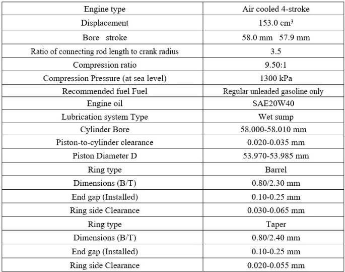
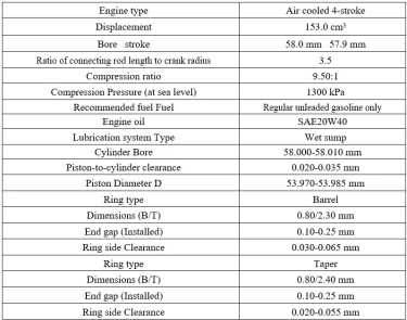
The engine chosen for the simulation study was the one equipped in YAMAHA-FZ-16-2008. The engine specifications are listed in the Table 1.
2.1. Boundary Pressure Calculation
The Reynolds’ equation was solved using boundary conditions at the leading and trailing edge of the piston ring. Here, the boundary conditions are the pressures developed at the leading and trailing edge of the ring. These pressures are depended on the direction of motion of the piston, the combustion chamber pressure and the inter-ring pressure between first and second compression ring, and vice versa.
Cylinder Pressure
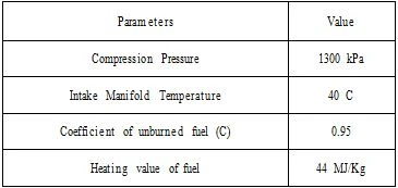
Combustion chamber pressure variation with crank angle was calculated using the process as described in previous literature [26-28].The different parameters used to calculate cylinder pressure were assumed as mentioned in Table 4 [29].
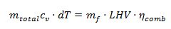
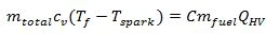
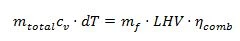
The energy balance equation used to calculate final temperature at the end of combustion process was as below [28],
 (1)
(1)
where,
• C_v is specific heat of gas mixture at constant volume.
• C is coefficient of unburned fuel, taken equal to (0.95)
• Q_HV is heating value of fuel, taken equal to 44MJ/kg
Consequently, cyclic volume of combustion chamber at TDCs and BDCs were calculated as follows;
Displaced or swept volume
where,
• C_v is specific heat of gas mixture at constant volume.
• C is coefficient of unburned fuel, taken equal to (0.95)
• Q_HV is heating value of fuel, taken equal to 44MJ/kg
Consequently, cyclic volume of combustion chamber at TDCs and BDCs were calculated as follows;
Displaced or swept volume 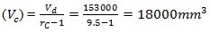
∴ Total Volume 
Hence, 
Similarly, 
Also, 
Connecting rod length; 
Where, n = 3.5 (Connecting rod length and crank radiud ratio)
The combustion chamber volume at every crank angle with spacing of 1^∘ was calculated as:
 (2)
(2)
Where,
 (3)
(3)
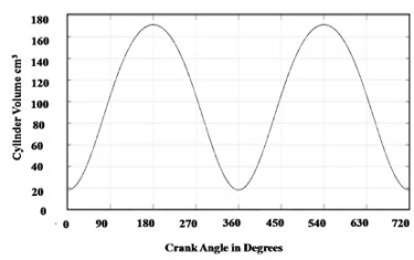
The variation of working volume with crank angle in graphical appearance was obtained as shown in figure 2.1.
Consequently, the pressure variation of each process was calculated.
Suction or Intake (Process 1 ─ 2)
Since P3’ = 1300 kPa, P2 is calculated using the adiabatic compression relation between points 3’ and 2 i.e.,
 (4)
(4)
Hence
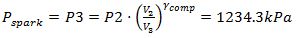
Compression (Process 2 ─ 3)
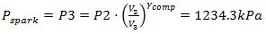
The pressure just before combustion starts,i.e. pressure at spark
 (5)
(5)
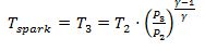
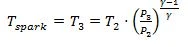
Similarly, the temperature of spark is calculated as
 (6)
(6)
Where, T2 =temperature of entrained air, was assumed to be 40∘C.
Combustion Process(Process 3 ─ 4)
The total mass of air-fuel mixture entrained inside the cylinder was calculated using ideal gas law at state 2, i.e.
 (7)
(7)
Where,
Rmix = Equivalent gas constant = 271 J-1kg-1
The duration of combustion was assumed to be 60 degrees of crank rotation.
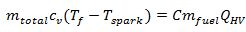
Temperature at the end of the combustion was calculated using energy balance equation i.e.
 (8)
(8)
Rearranging,
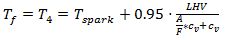 (9)
(9)
Where,
LHV = Lower heating value of the fuel (gasoline) = 44 MJ/kg
A/F = air mass to fuel mass ratio
cv= specific heat at constant volume
A/F=Air mass to fuel mass ratio
Pressure at the end of combustion was calculated using ideal gas law at state 4 i.e.
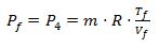 (10)
(10)
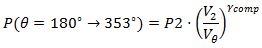
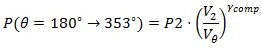
Finally, Pressure in combustion process between state 3 and 4 was calculated using Wieb function for mass fraction burned and MLK model as below:
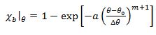 (11)
(11)
where, a = 5 and m=2, θo = 353
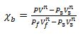 (12)
(12)
Rearranging,
 (13)
(13)
Expansion Process (Process 4 ─ 5)
The expansion process, since follows adiabatic path, is modeled with adiabatic relations.
 (14)
(14)
Exhaust Process (Process 5 ─ 6)
The exhaust process was modeled after the cosine interpolation method. The common interpolation method is linear interpolation, where the points are simply joined by straight line segments. Instead, often, a smoother interpolating function is desirable. The parameter μ defines where to estimate the value between the 2 known nodal points. It is 0 at first point and 1 at end point. Between these two points, the parameter μ ranges between 0 and 1, i.e. linearly spaced. Hence,
 (15)
(15)
Another parameter μ2θ is then calculated as:
 (16)
(16)
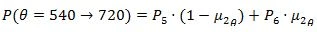
Then, the exhaust process is modeled as:
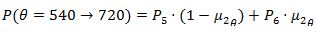 (17)
(17)
Where,

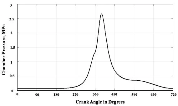
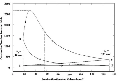
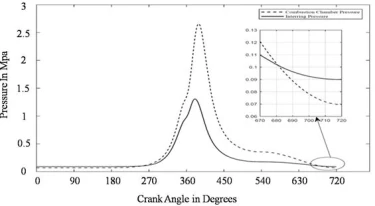
The whole calculation was done writing a MATLAB code. Figure 2 reveals cylinder pressure variation with crank angle. Consequently, Figure 3 and 4 demonstrates pressure- volume diagram of combustion chamber and variation of combustion chamber temperature with crank angle, respectively.
Figure 2. Combustion chamber pressure vs crank angle
Figure 3. P-V diagram
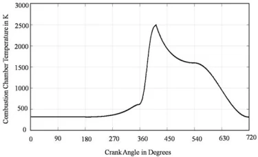
Figure 4 shows the variation of combustion chamber temperature with crank angle.
Figure 4. Combustion chamber temperature vs crank angle
2.2. Inter-ring Pressure
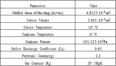
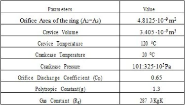
The model used for determination of inter-ring pressure variation is orifice-volume flow model [26, 30]. Here, the blow-down of combustion gases is modeled fluid flow through orifice connecting the crevice volume. The input parameters and their corresponding values used in this model to calculate inter-ring pressure between top and second compression rings are tabulated in table 2.3.
Table 3. Parameters for Inter-ring pressure calculation between top and second ring
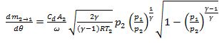
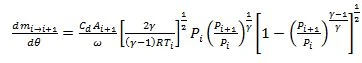
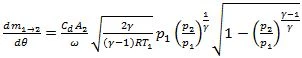
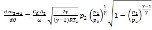
Here, the area of orifice is ring end area. Since, the study is focused only on top compression ring, inter ring pressure was calculated for the crevice volume between top compression ring and oil-scraper ring. Furthermore, sealing action of oil control ring was assumed negligible, thus, allowing the pressure between oil-scraper and oil control ring to be equal to crank-case pressure i.e. atmospheric pressure. Then, the mass flow rate for combustion gas flowing through the ring end gaps can be expressed as;
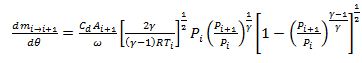 (18)
(18)
If Pi+1 exceed Pi, then the subscripts in the equation must be changed to include flow from crevice volume of pressure Pi+1 to Pi.
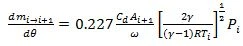
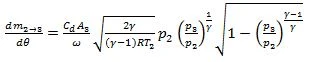
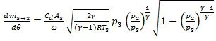
Here, the flow through the orifice increases as the pressure ratio Pi+1/Pi decreases and the flow velocity of gas becomes sonic when the value of pressure ratio becomes less than 0.546. Then the flow turns out to be choked and hence, further decrease in pressure ratio, flow rate becomes constant. So, a modified formula should be used for calculating the flow rate in choked condition which is given below;
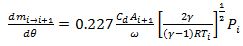 (19)
(19)
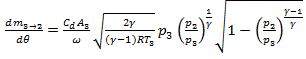
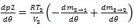
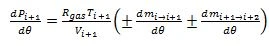
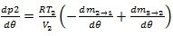
The rate of pressure change within the crevice volume can then be determined using following equations with modified equations for choked flow depending upon the pressure ratio.
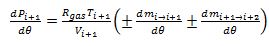 (20)
(20)
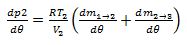
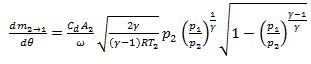
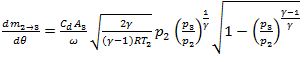
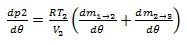
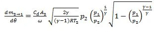
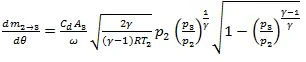
Case I ( p1> p2& p2> p3):
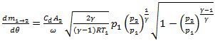 (21)
(21)
 (22)
(22)
 (23)
(23)
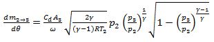
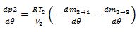
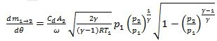
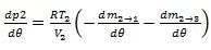
Case II ( p1> p2& p3> p2)
 (24)
(24)
 (25)
(25)
 (26)
(26)
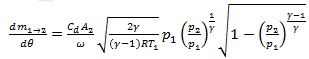
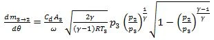
Case III ( p2> p1& p2> p3)
 (27)
(27)
 (28)
(28)
 (29)
(29)
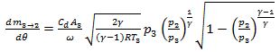
Case IV (p2> p1& p3> p2)
 (30)
(30)
 (31)
(31)
 (32)
(32)
The above sets of equations were solved using 4th order Runge-Kutta scheme.
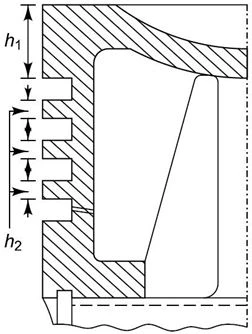
The orifice area, crevice volume and required dimensions of rings were calculated from the geometry of the piston groove given as below;
Figure 5. Groove for piston ring
Now, Width of the ring groove:

where, ha is axial width of ring
Piston to cylinder clearance,
End gap of the installed ring,
Area of orifice at ring end gap,
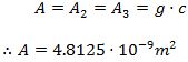
Crevice volume,
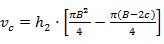 (33)
(33)
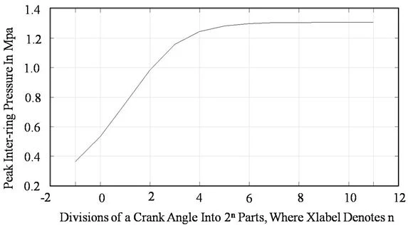
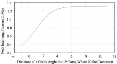
The Runge-Kutta solution was repeated for different crank angle division until grid independent solution was obtained. Grid independent solution was obtained when one degree crank angle was divided into 211 parts. The peak pressure convergence with decreasing grid
with converged value is shown in Figure 6.
Figure 6. Divisions of a crank angle into 2n parts, where Xlabel denotes n
Figure 7 demonstrates variation of inter-ring pressure with crank angle.
Figure 7. Inter-ring pressure variation with crank angle
For simulation, the top compression ring geometry of the engine specified in Table 1 was taken. The top compression ring lubrication and frictional losses between ring and liner were calculated by solving Reynolds equation.
3.1. Compression Ring Geometry
Ring profile of top compression ring is parabolic. The equation of the profile was obtained placing the origin of the co-ordinate system in the middle of ring axial width.
 (34)
(34)
Where, c and b are ring crown height and axial width respectively.
3.2. Reynolds Equation Solution
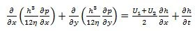
The piston ring-cylinder liner lubrication simulation was done using mathematical model considering hydrodynamic lubrication. For an isothermal, incompressible lubricant, the Reynolds equation can be used to solve the lubricant film pressure in hydrodynamic contacts [31].
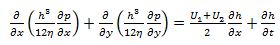 (35)
(35)
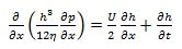
Neglecting the circumferential flow of lubricant in ring and setting U2 = 0 (since only piston moves) above equation reduces to following one-dimensional form:
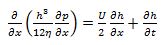 (36)
(36)
Where,
x = direction of piston axial motion
h = total thickness of lubricant film
i.e. h = hm(t) + hs(x)
hm(t) = minimum film thickness which varies with crank angle
hs(x) = profile of piston ring
p = hydrodynamic pressure
U = instantaneous speed of piston
∂h/∂t = squeeze film velocity term
η = dynamic viscosity
Squeeze film velocity is the effect of resistance to decrease in film thickness by lubricant due to rapid rate of change of film thickness in high speed region. This effect maintains the film thickness in dead center positions where piston speed is zero.
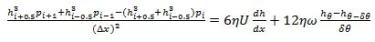
The above differential equation was discretized using finite difference method. So, the partial differential equation was changed into algebraic form which can be easily solved.
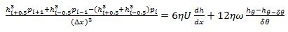 (37)
(37)
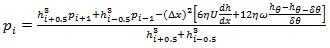
This equation can be arranged into following form for nodal pressure;
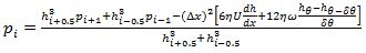 (38)
(38)
Here, fully flooded Gumbel’s boundary conditions was used [32]. Due to its computationally faster and significant results, this boundary condition is to be considered more appropriate for assessment of piston ring lubrication problems. This boundary condition can be expressed as;
For up ward motion of piston;
at x =b/2, pinlet = p101 = pcomb
at x = 0, pexit = p51 = pinter−ring
For down ward motion of piston
at x =−b/2, pinlet = p1 = pinter−ring
at x = 0, pexit = p51 = pcomb
First, minimum film thickness was assumed at certain crank angle. This crank angle was taken at maximum velocity position in intake stroke. The squeeze effect can be neglected for this position. Then, pressure distribution was found at this crank angle using the figure 16.
The solution was iterated changing the film thickness using under-relaxation technique till the hydrodynamic pressure generated balanced the applied loads. After that, solution was marched to another crank angle using forward Euler method. Consequently, the solution
procedure was repeated for the entire cycle of the engine. The assumed minimum film thickness was checked for convergence criteria. The solution procedures were repeated for further engine cycle until the film thickness converged.
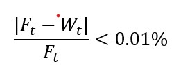
Nodal pressures were calculated using Gauss-Siedel iterative method. For finite difference solution, the piston ring profile was divided into 50 (coarse), 100 (medium) and 200 (fine) segments to observe the effect of node numbers on convergence. Results obtained by using 100segments showed with error percentage lying within 2 % with respect to fine grid. In addition to the following pressure convergence criteria was used for nodal pressure convergence.
For every nodal pressure,
 (39)
(39)
error ≤ 0.01
The hydrodynamic reaction force was calculated from nodal pressure using composite Simpson’s one third rule [33],
 (40)
(40)
This reaction force was balanced by applied loads quasi-statically i.e. load due to gas on back of ring and elastic load. Further more for this balancing following error criteria were used;
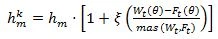
Minimum film thickness’s value was updated using the following relation;
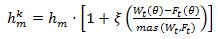 (41)
(41)
Where, ξ = 0.05
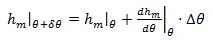
The forward Euler method used for crank angle marching with every one degree angle. This can be written as;
 (42)
(42)
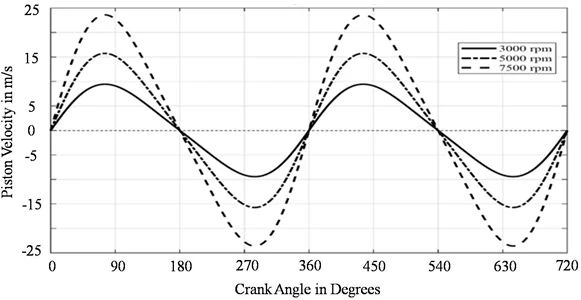
The solution was obtained for different RPM and crown heights. Piston velocity for different RPM are revealed in figure 8;
Figure 8. Piston velocity vs crank angle
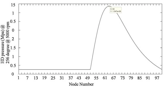
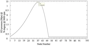
The calculation was done using MATLAB code. The distribution of pressure developed by the oil along the ring profile at 76 (downward stroke) and 256 (upward stroke) demonstrate in figures 9 and 10, respectively.
Figure 9. Pressure distribution along ring profile at 76
Figure 10. Pressure distribution along ring profile at 256 0C
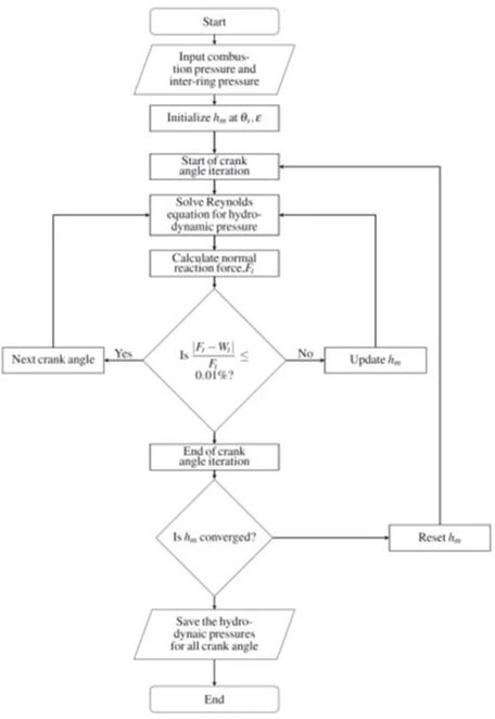
The flowchart of the complete numerical solution procedure for the Reynolds equation is as follows;
Figure 11. Numerical solution flow chart
3.2.1. Viscosity of Lubricants
Lubricants viscosity depends on the temperature. Temperature of the ring-liner system is different along the liner surface. As a result, temperature of the lubricant on the liner surface which depends on the ring-liner system temperature varies throughout the engine cycle. Generally, lubricant temperature is taken as a mean of ring outer surface temperature and cylinder liner’s temperature. Therefore, implementation of the temperature dependence of the viscosity would require not only a detailed model of the lubricant behavior but also the detailed prediction of the ring-liner system temperature. Integrating these entire models in the proposed transient lubrication model would be extremely difficult. Therefore, in the current study isothermal analysis is done assuming representative lubricant temperature of 120 0C. According to Vogel’s equation, the variation of viscosity with temperature can be assumed as [30];
 (43)
(43)

Where,
η = dynamic viscosity
T = temperature of lubricant taken as 120^∘ C
A, B and C are constants for a given lubricant whose value are 0.093⋅10^(-3) Ns/m^2, 1146.2500C, 124.7 0C respectively for the SAE 20W40.
3.2.2. Applied Load and Reaction Force
The gas pressure force and elastic stress force is the applied load on the back of the piston ring. Gas pressure force per unit circumferential length was found using either combustion pressure or inter-ring pressure for the top compression ring as below;
 (44)
(44)
Whereas ring elastic load was calculated using rings tension force at end gap. First, elastic pressure was calculated as;
 (45)
(45)
Where, P_e is assumed 0.37N.mm^(-2)
Subsequently, this pressure was used to calculate elastic load per unit circumferential length as;
 (46)
(46)
Accordingly, applied loads per unit length were calculated as;
 (47)
(47)
While the reaction force due to hydrodynamic action and asperity interaction were found by calculating hydrodynamic pressure. Hydrodynamic reaction force was calculated from the nodal pressures using Simpson’s one third rule.
Similarly, asperity load in case of mixed lubrication were found using equation as below [30].
 (48)
(48)
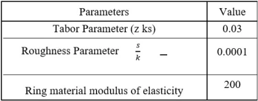
The parameters used to calculate asperity load are illustrated in table 3.1.
Table 4. Parameters for asperity load calculation
Friction Losses
Total friction force constitutes the viscous friction force due to hydrodynamic lubrication and asperity contacts friction due to mixed or partial lubrication.
Hydrodynamic friction component was found from viscous shear stress using the pressure distribution from Reynolds equation [34].
 (49)
(49)
Rate of change of pressure in axial width of ring was calculated using central difference method for middle nodes, and forward difference and backward difference for first and last node respectively, using the nodal pressures obtained from Reynolds equation’s solution.
The friction force due to asperity interaction was calculated using the relation [34].
 (50)
(50)
Here,
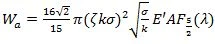
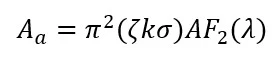
Aa and Wa are calculated as [35],
 (51)
(51)
Where,
• ζ = surface density of asperities peak on either surface
• σ = combined surface roughness
• k = the radius of curvature at the peak of asperities
• (ζσk) = known as Tabor parameter, it is surface roughness parameter
• A = apparent surface area of ring outer surface
• E' = composite Young’s modulus of the surfaces
• F2(λ) and F52(λ) = statistical functions
3.3. Average Power Loss
Now, instantaneous power loss due to friction in ring can be calculated from the friction forces. The instantaneous power losses were calculated by multiplying the friction force and velocity of a crank angle. During mixed lubrication, both hydrodynamic and boundary friction component’s loss was calculated and summed for the total loss at those crank angle. Then, average power loss was calculated from the instantaneous losses for the comparison of power loss due to engine speed and crown height variation. Average power loss is the average loss in one complete engine cycle, calculated as;
 (52)
(52)
Here, P(t) is instantaneous power loss and t is time period of complete engine cycle.
Here, Piston ring lubrication was analyzed solving Reynolds equation. The solution was found for different crank rotation and different crown height of the compression ring for understanding the effect of them on piston ring performance.
4.1. Effect of RPM
4.1.1. Film Thickness
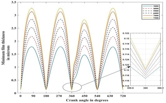
Minimum oil film thickness variation with crank angle was obtained from Reynolds equation for three different RPM keeping the crown height constant to 10 µm.
Figure 12. Minimum oil film thickness variation with crank angle for different RPM
The least value of minimum oil film thickness occurred in combustion process at top dead center for all RPM. This is due to the harsh condition of zero piston velocity and high load on the ring at that condition. Here, the minimum oil film thickness value at TDC and BDC are lower than the composite roughness value of surfaces, so, at these dead centers of all strokes, ring lubrication enters into mixed lubrication regime. Here, the oil film thickness value is lowest for expansion process, while others are comparable. As RPM increases, oil film thickness is also increased. This is due to significant hydrodynamic action at higher piston speed. As seen in figure, film thickness is greater at middle of all strokes; this is also due to hydrodynamic action as piston speed is greater in this zone. Consequently, there is no significant variation in minimum oil film thickness with increased RPM in critical locations of TDC and BDC. The variation of film thickness with change in RPM was found similar to the Jeng Y.R. et al [36].
4.1.2. Friction Force
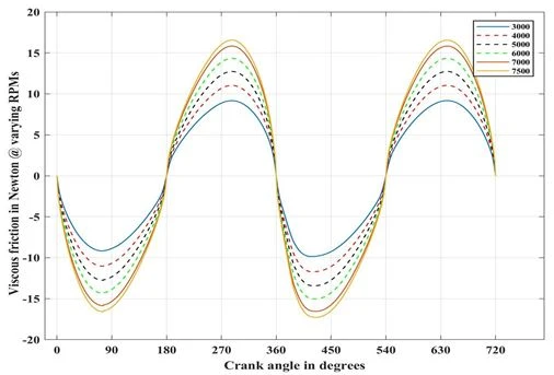
Variation of friction force with crank angle was obtained. Here, the total friction force was the summation of hydrodynamic and boundary friction force.
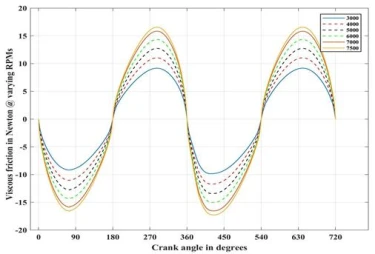
Figure 13. Variation of viscous force with crank angle for different RPM
Figure 13 illustrates the variation of viscous friction force with crank angle. Viscous friction force at mid of every stroke is maximum. Whereas, It is nearly equal to zero at TDC and BDC due to the formation of boundary lubrication [37]. Consequently, viscous friction force also increases with RPM.
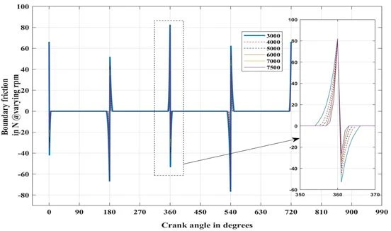
Figure 14. Boundary friction force variation with crank angle for different RPM
Variation of boundary friction force with crank angle is shown in Figure 14. Figure illustrates that the boundary friction occurs only in TDC and BDC. This is because of the asperity interaction between two ring-liner assemblies at the dead strokes [37]. Except dead strokes, boundary friction force is equal to zero because of greater oil film thickness which prevents the asperities contact. During combustion process, at TDC, boundary friction force becomes highest as a result of very high load and zero piston speed. Figure also demonstrates that the percentage of boundary lubrication portion decreases with increasing engine speed. At higher speed, ring enters lately to the boundary lubrication zone and leaves early from the critical zones. Otherwise, there is no significant variation in boundary friction values with increased RPM.
4.1.3. Average Power Loss
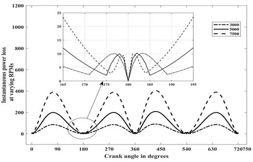
Figure 15. Variation of power loss with crank angle for different RPM
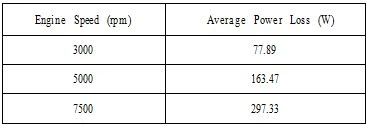
The variation of instantaneous power loss with crank angle rotation for different engine speed is shown in Figure 15. The power loss increases with engine speed. The calculated average power loss with different engine speed is tabulated Table 12.
Table 5. Average power loss for different engine speed
4.2. Effect of Crown Height
Crown height determines the wedge action and squeeze action in ring lubrication, so, it is a very significant ring geometric parameter. Greater the crown height more the ring is curved, and thus more the wedge angle. Here, film thickness, friction force variation and power loss with different crown height were found at engine speeds of 3000, 5000 and 7500 RPM.
4.2.1. Film Thickness
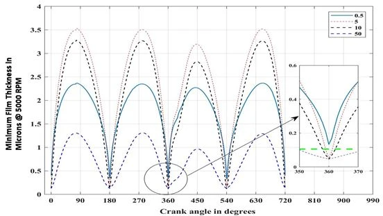
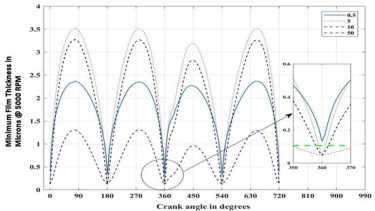
The minimum film thickness variation with crank angle for different ring crown height at 5000 RPM is shown in Figure 16.
Figure 16. Minimum film thickness variation for different crown height (in µm)
As revealed in figure, minimum film thickness is proportional to crown height. This is due to the increasing in wedge angle with crown height. However, after certain value of crown height, film thickness decreases. Whereas, the minimum film thickness at TDC and BDC increases with decreasing crown height. The squeeze action prevailed in those zones due to the slow motion of piston, increases the film thickness. This increased film thickness, decreases the wear in the liner and ring.
Figure 17. Minimum oil film thickness for different crown height (in µm) in mixed lubrication zone
The effect of crown height variation on minimum film thickness in different crank angle shows that the oil film thickness increases with crown height up to certain value. Beyond that value oil film thickness decreases nonetheless the crown height increases. Figure 17 shows the oil film thickness of different crown height with respective crank angle in the mixed lubrication zone for 7500 RPM. The above pattern of oil film thickness is similar to the earlier research [36].
4.2.2. Friction Force
The boundary friction force and viscous force with crank angle for different crown height were found. The Figure 18 and 19 illustrates the variation of these forces at constant RPM.
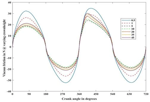
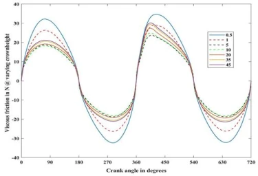
Figure 18. Viscous friction force variation for different crown height in µm
Figure 18 illustrates that the viscous friction force decreases with crown height. However, after certain value of crown height, viscous force again starts to increase. Increased crown height means greater film thickness. As there is inverse relation between viscous shear and film thickness, this decreases the viscous friction force. But for larger crown heights, viscous friction in power stroke is more than smaller crown heights. As crown height increases, initially viscous friction decreases but after certain value of crown height, it starts to increase. This is actually due to the increment of pressure gradient.
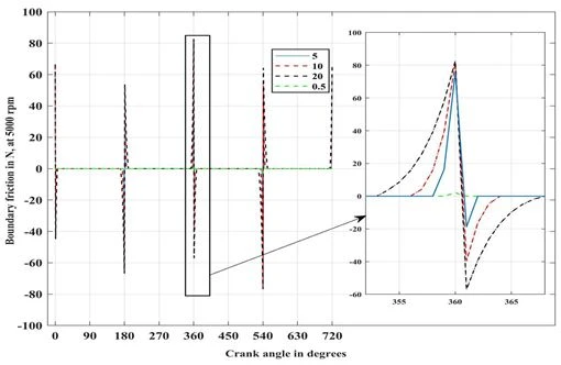
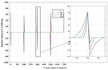
Figure 19. Boundary friction force variation for different crown height in µm
The Figure 19 demonstrates that the boundary friction force increases with crown height. This is due to diminishes of minimum film thickness at critical locations with increased crown height.
4.2.3. Average Power Loss
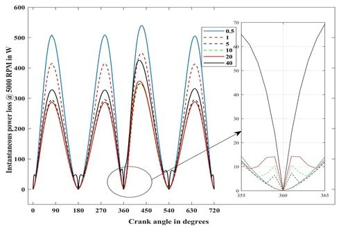
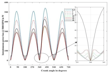
The power loss due to parasitic friction force for a complete engine cycle was found for different crown height. Total power loss was calculated by adding the viscous friction loss and boundary friction loss. Figure 20 shows the instantaneous power variation with crank angle for 5000 rpm of the complete engine cycle for different crown height of the top ring.
Figure 20. Power loss in compression ring due to friction for various crown heights in µm
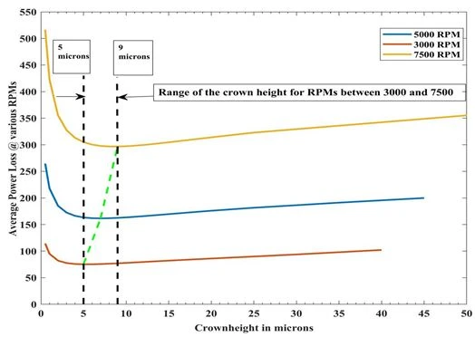
Average power losses for a complete engine cycle were calculated by varying the crown heights for different rpm using the instantaneous total power losses. The Figure 21 illustrates the range of optimum crown height for different engine rpm.
Figure 21. Average power loss variation with crown hight for different RPM
The graph shows a range of crown height for minimum average power loss considering different rpm. The obtained result confirms that the range of 5 to 9 micron meter crown height is better for minimizing power loss at various rpm.
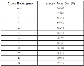
Table 6. Average power loss for different crown height
The above calculated values show that the minimum power loss is obtained in 5 to 9 µm crown height. The obtained results are comparable to the prior research [38].
Lubrication phenomena of piston top compression ring was studied under the hydrodynamic as well as mixed lubrication regimes to predict the crown height of piston compression ring that would give least power loss during total engine cycle.
The different numerical methods were used for mathematical modeling that contains the characteristic of piston crown height which generates least power loss as well as traded-off boundary friction forces.
The first step was to generate a satisfactory combustion chamber pressure v/s crank angle relations using simplified models, under the assumption of working fluid (fuel and air mixture) as an ideal gas. This provided as the basis for calculating the pressure inside the inter-ring crevice volumes. This task was performed by modeling the gas flow through piston ring orifices like one dimensional isentropic flow. The piston ring crevice volumes and orifices were treated as a labyrinth seal model through which the combustion gases flow depressurizedthe crank case pressure. Runge-Kutta fourth order scheme was employed to solve the differential equation which governs the one dimensional flow of gases through an orifice.
In the analysis, combustion chamber pressure and Inter-ring gas pressures variation with crank angle were taken as the boundary condition for solving Reynolds equation. Axisymmetric (one dimensional) Reynolds equation (2nd order partial differential equation) was solved using Finite Difference Method.
First, solution of the model was found for speeds 3000, 5000 and 7500 rpm of the selected engine with a fixed crown height of 10 µm. Film thicknesses and viscous friction both increased with speed, while there was no significant effect of rpm on boundary friction. Then, the model was again solved by varying the crown height of compression ring for different rpm. The film thickness was increased with crown height up to certain value, then decreases. However, the lower crown heights have better minimum film thickness at critical locations. The viscous friction decreases with the increased crown height and boundary friction force increases with increasing crown height. Moreover, average power losses were also calculated for different crown height. The average power loss first decreased with the increment of crown height and again started to increase beyond certain value of crown height for all rpm.The crown height of 5, 7 and 9 µm showed the minimum average power loss for all rpm.Although,the power loss of these three crown heights is almost same for all engine speeds, 5 µm crown height can be selected due to the reason that the lower crown height furnishes the better film thickness at critical zones.
Thus, in this study, the ring lubrication study was performed in compression ring for minimum power loss by developing numerical model for piston ring in mixed lubrication regime by stating piston velocity, the pressure history of combustion chamber and inter-ring pressure, effective surface roughness and viscosity.
We would like to take this opportunity to express our profound gratitude and deep regards to the Department of Automobile and Mechanical Engineering, Institute of Engineering (IOE), Thapathali Campus for providing us the opportunity to initiate this project.
In addition, we would like to extend our sincere thanks to Raj Kumar Chaulagain, Head of the Department, Department of Automobile and Mechanical Engineering, Thapathali Campus for providing necessary information regarding the project. We would also like to express our sincere thanks to library of Thapathali Campus for providing access to the computers for the simulation.
1 J.C. Bell, Engine lubricants, in: C.M. Taylor (Ed.) Tribology Series, Elsevier (1993) 287.
2 R.J. Chittenden, M. Priest, Analysis of the Piston Assembly, Bore Distortion and Future Developments, in: C.M. Taylor (Ed.) Tribology Series, Elsevier (1993) 241.
3 D. Dowson, Piston Assemblies; Background and Lubrication Analysis, in: C.M. Taylor (Ed.) Tribology Series, Elsevier (1993) 213.
4 A. Ronen, I. Etsion, Y. Kligerman, Tribology Transactions 44(3) (2001) 359.
5 M. Nakano, A. Korenaga, A. Korenaga, K. Miyake, T. Murakami, Y. Ando, H. Usami, S. Sasaki, Tribology Letters 28(2) (2007) 131.
6 A. Ramesh, W. Akram, S.P. Mishra, A.H. Cannon, A.A. Polycarpou, W.P. King, Tribology International 57 (2013) 170.
7 Z. Ma, W. Bryzik, Tribology Transactions 49(3) (2006) 315.
8 T.H.C. Childs, Dry and boundary lubricated sliding friction and wear for engine component materials, in: C.M. Taylor (Ed.) Tribology Series, Elsevier (1993) 51.
9 A. Wolff, Tribology Transactions 57(4) (2014) 653.
10 D.A. Jones, Elastohydrodynamic Lubrication Theory, in: C.M. Taylor (Ed.) Tribology Series, Elsevier (1993) 15.
11 C. Delprete, A. Razavykia, Proceedings of the Institution of Mechanical Engineers, Part J: Journal of Engineering Tribology 232 (2017).
12 S. Furuhama, T. Sumi, A Dynamic Theory of Piston-Ring Lubrication: 3rd Report, Measurement of Oil Film Thickness, Bulletin of JSME 4 (1961) 744.
13 M.-T. Ma, I. Sherrington, E.H. Smith, Proceedings of the Institution of Mechanical Engineers, Part J: Journal of Engineering Tribology 211 (1997) 1.
14 O. Akalin, G.M. Newaz, Journal of Tribology 123 (1999) 211.
15 R.A. Mufti, M. Priest, R.J. Chittenden, Proceedings of the Institution of Mechanical Engineers, Part D: Journal of Automobile Engineering 222 (2008) 1441.
16 J. Forero, G. Valencia, J. Rojas, Lubricants 8 (2020) 83.
17 Y. Kligerman, I. Etsion, A. Shinkarenko, Improving Tribological Performance of Piston Rings by Partial Surface Texturing, Journal of Tribology-transactions of The Asme 127 (2005) 632.
18 A. Zavos, P. Nikolakopoulos, Lubrication Science 27 (2015) 151.
19 C. Shen, M. Khonsari, Tribology International 101 (2016).
20 S.A. Mohamad, X. Lu, Q. Zheng, Proceedings of the Institution of Mechanical Engineers, Part J: Journal of Engineering Tribology 229 (2015) 989.
21 S. Mohamad, X. Lu, Q. Zheng, Advances in Mechanical Engineering 7 (2014) 837960.
22 C. Gu, X. Meng, Y. Xie, Y. Yang, Tribology International 94 (2015) 591.
23 V. Zin, F. Agresti, S. Barison, L. Colla, A. Gondolini, M. Fabrizio, IEEE Transactions on Nanotechnology 12 (2013) 751.
24 Q. Wan, Y. Jin, P. Sun, Y. Ding, Procedia Engineering 102 (2015) 1038.
25 M. Laad, V.K.S. Jatti, Journal of King Saud University - Engineering Sciences 30 (2018) 116.
26 B.H. John, Internal Combustion Engine Fundamentals, Second Edition, 2nd edition. ed., McGraw-Hill Education, New York (2018).
27 N.C. Blizard, J.C. Keck, SAE Transactions 83 (1974) 846.
28 J.B. Heywood, Internal Combustion Engine Fundamentals, McGraw-Hill (1988).
29 H.M. Cheung, J.B. Heywood, SAE Transactions 102 (1993) 2292.
30 W. Chong, S. Howell-Smith, M. Teodorescu, N. Vaughan, Proceedings of the Institution of Mechanical Engineers, Part J: Journal of Engineering Tribology 227 (2013) 154.
31 O. Akalin, G. Newaz, Journal of Tribology-transactions of The Asme - J TRIBOL-TRANS ASME 123 (2001) 211.
32 C. Delprete, A. Razavykia, Modeling of Oil Film Thickness in Piston Ring/Liner Interface 6(3) (2017).
33 P. Bansal, A. Chattopadhayay, V. Agrawal, Tribology Transactions 58 (2015) 316.
34 S. Matele, K. Pandey, Proceedings of the Institution of Mechanical Engineers, Part J: Journal of Engineering Tribology 232 (2018) 1365.
35 J.A. Greenwood, J.H. Tripp, Proceedings of the Institution of Mechanical Engineers 185 (1970) 625.
36 Y.-R. Jeng, Tribology Transactions 35 (1992) 696.
37 Y. Ng, S.h. Hamdan, W. Chong, Jurnal Tribologi 17 (2018) 2.
38 S.-K. Jeng, S.-W. Lee, Microwave and Optical Technology Letters 5 (1992) 682.
S.P. Adhikari, S. Gewali, Bijaya Galami, Birat Sitaula, Simulation based analysis to study the effect of compression ring crown height in ring liner assembly on the performance of four stroke petrol engine, UNEC J. Eng. Appl. Sci. 3(1) (2023) 45-68 https://doi.org/10.61640/ujeas.2023.0508
Anyone you share the following link with will be able to read this content:
This article is licensed under the Creative Commons Attribution ( CC BY 4.0 ) License, which permits unrestricted use, distribution, and reproduction in any medium, provided the original author and source are credited.


J.C. Bell, Engine lubricants, in: C.M. Taylor (Ed.) Tribology Series, Elsevier (1993) 287.
R.J. Chittenden, M. Priest, Analysis of the Piston Assembly, Bore Distortion and Future Developments, in: C.M. Taylor (Ed.) Tribology Series, Elsevier (1993) 241.
D. Dowson, Piston Assemblies; Background and Lubrication Analysis, in: C.M. Taylor (Ed.) Tribology Series, Elsevier (1993) 213.
A. Ronen, I. Etsion, Y. Kligerman, Tribology Transactions 44(3) (2001) 359.
M. Nakano, A. Korenaga, A. Korenaga, K. Miyake, T. Murakami, Y. Ando, H. Usami, S. Sasaki, Tribology Letters 28(2) (2007) 131.
A. Ramesh, W. Akram, S.P. Mishra, A.H. Cannon, A.A. Polycarpou, W.P. King, Tribology International 57 (2013) 170.
Z. Ma, W. Bryzik, Tribology Transactions 49(3) (2006) 315.
T.H.C. Childs, Dry and boundary lubricated sliding friction and wear for engine component materials, in: C.M. Taylor (Ed.) Tribology Series, Elsevier (1993) 51.
A. Wolff, Tribology Transactions 57(4) (2014) 653.
D.A. Jones, Elastohydrodynamic Lubrication Theory, in: C.M. Taylor (Ed.) Tribology Series, Elsevier (1993) 15.
C. Delprete, A. Razavykia, Proceedings of the Institution of Mechanical Engineers, Part J: Journal of Engineering Tribology 232 (2017).
S. Furuhama, T. Sumi, A Dynamic Theory of Piston-Ring Lubrication: 3rd Report, Measurement of Oil Film Thickness, Bulletin of JSME 4 (1961) 744.
M.-T. Ma, I. Sherrington, E.H. Smith, Proceedings of the Institution of Mechanical Engineers, Part J: Journal of Engineering Tribology 211 (1997) 1.
O. Akalin, G.M. Newaz, Journal of Tribology 123 (1999) 211.
R.A. Mufti, M. Priest, R.J. Chittenden, Proceedings of the Institution of Mechanical Engineers, Part D: Journal of Automobile Engineering 222 (2008) 1441.
J. Forero, G. Valencia, J. Rojas, Lubricants 8 (2020) 83.
Y. Kligerman, I. Etsion, A. Shinkarenko, Improving Tribological Performance of Piston Rings by Partial Surface Texturing, Journal of Tribology-transactions of The Asme 127 (2005) 632.
A. Zavos, P. Nikolakopoulos, Lubrication Science 27 (2015) 151.
C. Shen, M. Khonsari, Tribology International 101 (2016).
S.A. Mohamad, X. Lu, Q. Zheng, Proceedings of the Institution of Mechanical Engineers, Part J: Journal of Engineering Tribology 229 (2015) 989.
S. Mohamad, X. Lu, Q. Zheng, Advances in Mechanical Engineering 7 (2014) 837960.
C. Gu, X. Meng, Y. Xie, Y. Yang, Tribology International 94 (2015) 591.
V. Zin, F. Agresti, S. Barison, L. Colla, A. Gondolini, M. Fabrizio, IEEE Transactions on Nanotechnology 12 (2013) 751.
Q. Wan, Y. Jin, P. Sun, Y. Ding, Procedia Engineering 102 (2015) 1038.
M. Laad, V.K.S. Jatti, Journal of King Saud University - Engineering Sciences 30 (2018) 116.
B.H. John, Internal Combustion Engine Fundamentals, Second Edition, 2nd edition. ed., McGraw-Hill Education, New York (2018).
N.C. Blizard, J.C. Keck, SAE Transactions 83 (1974) 846.
J.B. Heywood, Internal Combustion Engine Fundamentals, McGraw-Hill (1988).
H.M. Cheung, J.B. Heywood, SAE Transactions 102 (1993) 2292.
W. Chong, S. Howell-Smith, M. Teodorescu, N. Vaughan, Proceedings of the Institution of Mechanical Engineers, Part J: Journal of Engineering Tribology 227 (2013) 154.
O. Akalin, G. Newaz, Journal of Tribology-transactions of The Asme - J TRIBOL-TRANS ASME 123 (2001) 211.
C. Delprete, A. Razavykia, Modeling of Oil Film Thickness in Piston Ring/Liner Interface 6(3) (2017).
P. Bansal, A. Chattopadhayay, V. Agrawal, Tribology Transactions 58 (2015) 316.
S. Matele, K. Pandey, Proceedings of the Institution of Mechanical Engineers, Part J: Journal of Engineering Tribology 232 (2018) 1365.
J.A. Greenwood, J.H. Tripp, Proceedings of the Institution of Mechanical Engineers 185 (1970) 625.
Y.-R. Jeng, Tribology Transactions 35 (1992) 696.
Y. Ng, S.h. Hamdan, W. Chong, Jurnal Tribologi 17 (2018) 2.
S.-K. Jeng, S.-W. Lee, Microwave and Optical Technology Letters 5 (1992) 682.