UNEC Journal of Engineering and Applied Sciences Volume 2, No 2, pages 49-55 (2022) Cite this article, ![]() 1454
1454
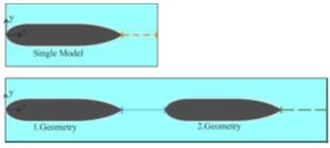
Fluid mechanics is used in many fields. Particularly in the fields of mechanical engineering, there are studies on increasing energy efficiency with different experimental studies in geometry optimization. With obstructed flow tests, the flow structure around the desired geometry is investigated with special test setups, and information about the flow characteristics around the geometry in terms of aerodynamics and hydrodynamics can be obtained, and energy loss can be reduced by making the necessary optimizations. In this context, many studies were carried out. First of all, studies were carried out on autonomous aircraft. Some studies in this field: [1-6]. Three quarters of our world is covered by water. For this reason, above and below the seas have been very important from the past to the present in terms of social, economic and defense. On this context, many researchers have turned to design, apply and develop new generation manned or unmanned autonomous underwater vehicles (AUV) in the fields of defense, industry and research: [6-12]. AUVs are vehicles that can be sent to a specific target by being remotely controlled or programmed with the stored specific energy. They can be used for more complex tasks. For some complex missions, more than one autonomous vehicle may be needed as given in some studies on multiple AUVs: [13-19]. However, multi-array AUVs can have hydrodynamic interactions with each other while in motion. For this reason, flow hydrodynamics needs to be carefully investigated. In this study, the flow characteristics around the blunt nose and conical stern models with single and tandem arrangements were compared by using the PIV method. Experiments were carried out under uniform flow conditions at u=100 mm/s and corresponding Reynolds number Re=2x10⁴. The characteristic length-diameter ratio of the model used in the experiments is L/D=5. The space ratio between models in tandem arrangement is dimensionless G/L=0.3. Up to date, the proposed model arrangement has not been encountered in the open literature with PIV apart from the present group.
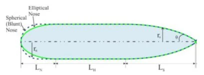
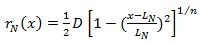
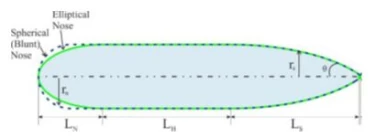
The geometry design and size of the model were determined to form a streamlined underwater vehicle model by using the [20] equations 1 and 2 given below.
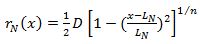 (1)
(1)
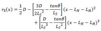 (2)
(2)
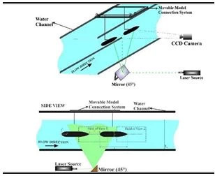
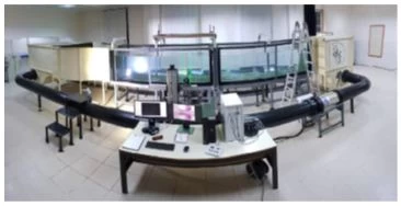
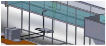
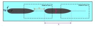
In these equations, x is the axial distance from the nose to the stern end. Myring angular parameter of the stern and the nose curvature form of the geometry are taken as θ≅30° and n=4, respectively. The PIV measurement conducted using the water channel and a Nd:YAG laser working in synchronization with a camera in the Advanced Mechanical Engineering laboratory of Osmaniye Korkut Ata University.To obtain flow charecteristics, experimental setup of the water channel for laser illumination and PIV measurement of field of views is shown in Figure 2 and 3. The space between the two identical geometries is denoted by G.
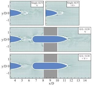
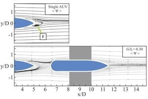
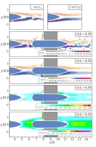
In this study, alteration of the instantaneous velocity vector field (V) and time-averaged velocity vector field <V> prepared for the comparison of the PIV experiment analysis results around the stern section of single and tandem arrangements of two identical models with blunt nose and conical stern made under uniform flow conditions at Re=2x10⁴ in Figure 6. In Figure 7, time-averaged streamline topology <Ψ>. Instantaneous vorticity contours ωL/U∞, time-averaged vorticity contours <ωL/U∞>, time-averaged streamwise velocity fluctuations contours <urms/U∞> and time-averaged cross-streamwise velocity fluctuations contours <vrms/U∞> are given in Figure 8.
When the instantaneous vector field (V) in the wake region of a single model in Figure 7 is investigated, it is observed that the vortex structure increases due to the unsteady motions of the vectors. It is clearly observed that the vectors keep spreading along the geometry symmetry axis out of the field of view like a similar manner of the Von Karman vortex street. At the space ratio of G/L=0.30, the unsteady in the instantaneous vector field (V) in the first geometry wake region is considerably higher than in the single model and the second model wake region. When the time-average vector fields of the single model and tandem arrangement models are investigated, it seems cleaner than the instantaneous vectors. However, it has been observed that the vector structures behind the second model are smaller and less effective than the vector structures behind the single model. Because the momentum of the flow passing over the second model decreases due to friction and other flow effects. This situation shows that the vortex structure is more complex compared to a single model. The effect of the nose part of the second model on the flow structure in the first model wake region is clearly observed.
When the time-averaged streamline topologies <Ψ> are investigated, it is observed that a rotational focal point F1 is formed behind the blunt nose and conical stern single model. At the space ratio of G/L=0.30, no focal point or other structures were not observed in the first, and the second model wake region.
As a result of PIV analyzes performed under uniform flow conditions of single and tandem arrangements of two models with blunt nose- conical stern, it was observed that instantaneous vorticity countours ωL/U∞, and time-averaged vorticity countours <ωL/U∞> to the positive and negative values were formed. It has been observed that the time-averaged vorticity contours are quite symmetrical in single and tandem arrangements of two models. When the instantaneous vorticity contours are examined, it has been observed that the vorticity contours in the first model wake region interacted with the nose of the second model, blocking the flow and breaking the vortices into smaller pieces. When we compare the positions of the time- averaged vorticity countours <ωL/U∞> here with the single and G/L=0.30 cases, the time-averaged vorticity countours <ωL/U∞> occur at a far distance from the stern in the single model wake ragion, but in the case of G/L=0.30, the values for the first geometry get smaller and come to the stern, while in the second model wake region they were located closer to the stern than in the single model wake region. It is seen that the area covered by the time averaged cross-streamwise velocity fluctuation contours are larger than the time averaged streamwise velocity fluctuation contours wake region in the case of G/L=0.30. As a result, it was observed that the time averaged cross-streamwise velocity fluctuation were more. It was observed that the values in the first model wake region at the G/L=0.30 state increased, and the vorticity structure increased compared to the single model wake region. In addition, it was observed that the wake region approached the model. In addition, it was observed that the vortex structures in the second model wake region were broke and becomesmaller and intertwined.
In this study, instantaneous and time-averaged flow characteristics of the single model and tandem arrangement models at the ratio of G/L=0.30 are investigated using the PIV method. The following observations were obtained. The vector field and vortex structures behind the second model are smaller and less impressive on the body in the downstream body of the dual arrangement than in the single model. The streamline topology behind the downstream body is more streamlined and have less separation with respect to the single model case. Around the flow structures the nose of the second model due to the interaction and fragment into parts wake coming from the first body have more scattered region than the front model wake, which can be used to develop new flow control method. The time averaged cross-streamwise velocity fluctuations are greater than the time averaged streamwise velocity fluctuation in the case of G/L=0.30. All of the time-averaged flow structures demonstrated that the second body critical points become closer to the stern section of the downstream body for the dual body arrangement. In future, both experimental and numerical studies, active or passive flow control methods along with force measurement can be performed not only for the present arrangements but also side-by-side and staggered configurations.
The authors would like to acknowledge the Scientific and Technological Research Council of Turkey (TUBITAK) under Contract No. 214M318 and thank the Advanced Fluid Mechanics PIV laboratory of Osmaniye Korkut Ata University, Turkey for using the water channel and measurement systems. In addition, the authors thank the OKU Scientific Research Projects Unit for their support with the project number OKÜBAP-2022-PT2-032.
1 K.M. Byrne, Naval Postgraduate School Monterey CA (1998).
2 P. Ananthakrishnan, and K.Q. Zhang, Conference Proceedings (Cat. No. 98CH36259), Nice (1998) 1059.
3 M. Husaini, Z. Samad, and M. Rizal, “CFD Simulation of Cooperative AUV Motion.” P.Pinang. University Sains Malaysia (2009).
4 B. Yaniktepe, and D. Rockwell, AIAA Journal 42(3) (2004) 513
5 B. Yaniktepe, and D. Rockwell, AIAA journal 43(7) (2005) 1490.
6 B. Yaniktepe, Gazi Üniversitesi Fen Bilimleri Dergisi Part: C Tasarım ve Teknoloji 4(4) (2016) 247.
7 E. Akbudak, B. Yaniktepe, E. Sekeroğlu, Ö. Kenan, and M, Ozgoren, Osmaniye Korkut Ata University Journal of the Institute of Science and Technology 5(special issue) (2022) 135.
8 Kilavuz, T. Durhasan, M. Ozgoren, F. Sarigiguzel, B. Sahin, L.A. Kavurma-cioglu, H. Akilli, E. Sekeroglu, and B. Yaniktepe, J Mar Sci Technol, (2022a):
9 Kilavuz, F. Sarigiguzel, M. Ozgoren, T. Durhasan, B. Sahin, L.A. Kavurma-cioglu, E. Sekeroglu, and B. Yaniktepe, European Journal of Mechanics-B/Fluids 92 (2022b) 226.
10 M. Ozgoren, B. Sahin, A. Kahraman, H. Akilli, and C. Canpolat, C, Euromech fluid mechanics conferans -8 (EFMC-8) Germany (2010) 3.
11 P. Rattanasiri, P.A. Wilson, and A.B. Phillips, In 2012 IEEE/OES Autonomous Underwater Vehicles (AUV) IEEE (2012) 1.
12 12. F. Sarigiguzel, A. Kilavuz, M. Ozgoren, T. Durhasan, B. Sahin, L.A. Kavurmacioglu, H. Akilli, E. Sekeroglu, and B. Yaniktepe, Ocean Engineering 253 (2022) 111174, ISSN 0029-8018,
13 Schulz, B. Hobson, M. Kemp, J. Meyer, R. Moody, H. Pinnix, and M.S.Clair, Proc. 13th Unmanned Untethered Submersible Technology (2003).
14 Arsie, K. Savla, and E. Frazzoli, IEEE Transactions on Automatic Control, 54(10) (2009) 2302.
15 J. Deng, X.M. Shao, and Z.S. Yu, Physics of fluids 19(11) (2007) 113104.
16 E. Fiorelli, P.Leonard, P. Bhatta, D.A. Paley, R. Bachmayer, and D.M. Fratantoni, IEEE journal of oceanic engineering 31(4) (2006) 935.
17 W. Tian, Z. Mao, F. Zhao, and Z. Zhao, Complexity (2017) 5769794.
18 B.J. Goode, A.J. Kurdila, and M.J. Roan, J. Dyn. Sys., Meas., Control 134(1) (2012) 011025.
19 Huang, D. Zhu, and B. Sun, Engineering Applications of Artificial Intelligence 50 (2016) 192.
20 D.F. Myring, The Aeronautical Journal 27 (1976) 186.
E. Akbudak, E. Şekeroğlu, B. Yaniktepe, Ö. Kenan, M. Özgören, Investigation of flow characteristics around a blunt nose and conical stern geometry with single and tandem arrangements, UNEC J. Eng. Appl. Sci. 2(2) (2022) 49-55
Anyone you share the following link with will be able to read this content:
This article is licensed under the Creative Commons Attribution ( CC BY 4.0 ) License, which permits unrestricted use, distribution, and reproduction in any medium, provided the original author and source are credited.


K.M. Byrne, Naval Postgraduate School Monterey CA (1998).
P. Ananthakrishnan, and K.Q. Zhang, Conference Proceedings (Cat. No. 98CH36259), Nice (1998) 1059.
M. Husaini, Z. Samad, and M. Rizal, “CFD Simulation of Cooperative AUV Motion.” P.Pinang. University Sains Malaysia (2009).
B. Yaniktepe, and D. Rockwell, AIAA Journal 42(3) (2004) 513
B. Yaniktepe, and D. Rockwell, AIAA journal 43(7) (2005) 1490.
B. Yaniktepe, Gazi Üniversitesi Fen Bilimleri Dergisi Part: C Tasarım ve Teknoloji 4(4) (2016) 247.
E. Akbudak, B. Yaniktepe, E. Sekeroğlu, Ö. Kenan, and M, Ozgoren, Osmaniye Korkut Ata University Journal of the Institute of Science and Technology 5(special issue) (2022) 135.
Kilavuz, T. Durhasan, M. Ozgoren, F. Sarigiguzel, B. Sahin, L.A. Kavurma-cioglu, H. Akilli, E. Sekeroglu, and B. Yaniktepe, J Mar Sci Technol, (2022a):
Kilavuz, F. Sarigiguzel, M. Ozgoren, T. Durhasan, B. Sahin, L.A. Kavurma-cioglu, E. Sekeroglu, and B. Yaniktepe, European Journal of Mechanics-B/Fluids 92 (2022b) 226.
M. Ozgoren, B. Sahin, A. Kahraman, H. Akilli, and C. Canpolat, C, Euromech fluid mechanics conferans -8 (EFMC-8) Germany (2010) 3.
P. Rattanasiri, P.A. Wilson, and A.B. Phillips, In 2012 IEEE/OES Autonomous Underwater Vehicles (AUV) IEEE (2012) 1.
12. F. Sarigiguzel, A. Kilavuz, M. Ozgoren, T. Durhasan, B. Sahin, L.A. Kavurmacioglu, H. Akilli, E. Sekeroglu, and B. Yaniktepe, Ocean Engineering 253 (2022) 111174, ISSN 0029-8018,
Schulz, B. Hobson, M. Kemp, J. Meyer, R. Moody, H. Pinnix, and M.S.Clair, Proc. 13th Unmanned Untethered Submersible Technology (2003).
Arsie, K. Savla, and E. Frazzoli, IEEE Transactions on Automatic Control, 54(10) (2009) 2302.
J. Deng, X.M. Shao, and Z.S. Yu, Physics of fluids 19(11) (2007) 113104.
E. Fiorelli, P.Leonard, P. Bhatta, D.A. Paley, R. Bachmayer, and D.M. Fratantoni, IEEE journal of oceanic engineering 31(4) (2006) 935.
W. Tian, Z. Mao, F. Zhao, and Z. Zhao, Complexity (2017) 5769794.
B.J. Goode, A.J. Kurdila, and M.J. Roan, J. Dyn. Sys., Meas., Control 134(1) (2012) 011025.
Huang, D. Zhu, and B. Sun, Engineering Applications of Artificial Intelligence 50 (2016) 192.
D.F. Myring, The Aeronautical Journal 27 (1976) 186.